An optical fiber liquid level sensor and its measuring method

A liquid level sensor and measurement method technology, applied in the field of sensors, can solve the problems of difficult manufacturing of deformed teeth, expensive wavelength demodulation equipment, etc., and achieve the effect of good electromagnetic anti-interference performance, cheap price, and easy installation

Active Publication Date: 2019-02-01
河北微探科技有限公司
View PDF4 Cites 1 Cited by
  • Summary
  • Abstract
  • Description
  • Claims
  • Application Information

AI Technical Summary

Problems solved by technology

The optical fiber microbend sensor needs to design movable teeth and fixed teeth. When under pressure, the elastic diaphragm drives the movable teeth to move towards the fixed teeth, causing the optical fiber to bend slightly. Its advantage is that the measurement accuracy is high, and the disadvantage is that the deformation teeth Difficult; the optical fiber F‐P cavity liquid level sensor is designed according to the principle of the F‐P cavity interferometer. The F‐P cavity is usually composed of an elastic diaphragm and an optical fiber end face. It has the advantage of simple structure, but it needs to consider temperature, light source The impact of strong changes on the measurement accuracy; the fiber grating liquid level sensor obtains pressure information through the modulation of the liquid pressure on the center wavelength of the grating. Its advantages are high measurement accuracy and easy to form a distributed measurement system. Its disadvantage is the wavelength demodulation equipment Expensive, need to solve problems such as desensitization

Method used


Image

  • An optical fiber liquid level sensor and its measuring method
  • An optical fiber liquid level sensor and its measuring method
  • An optical fiber liquid level sensor and its measuring method

Examples


Embodiment Construction

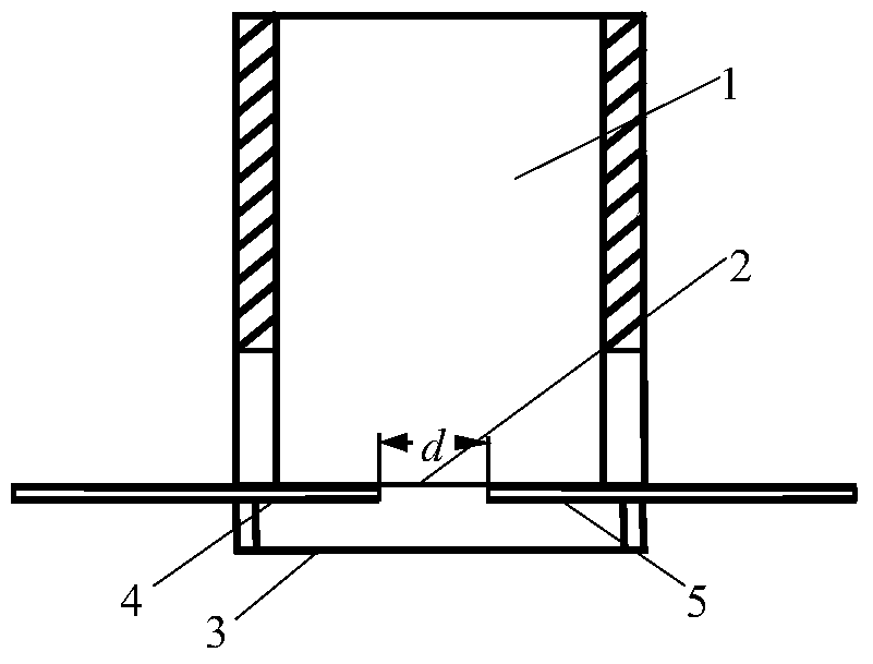
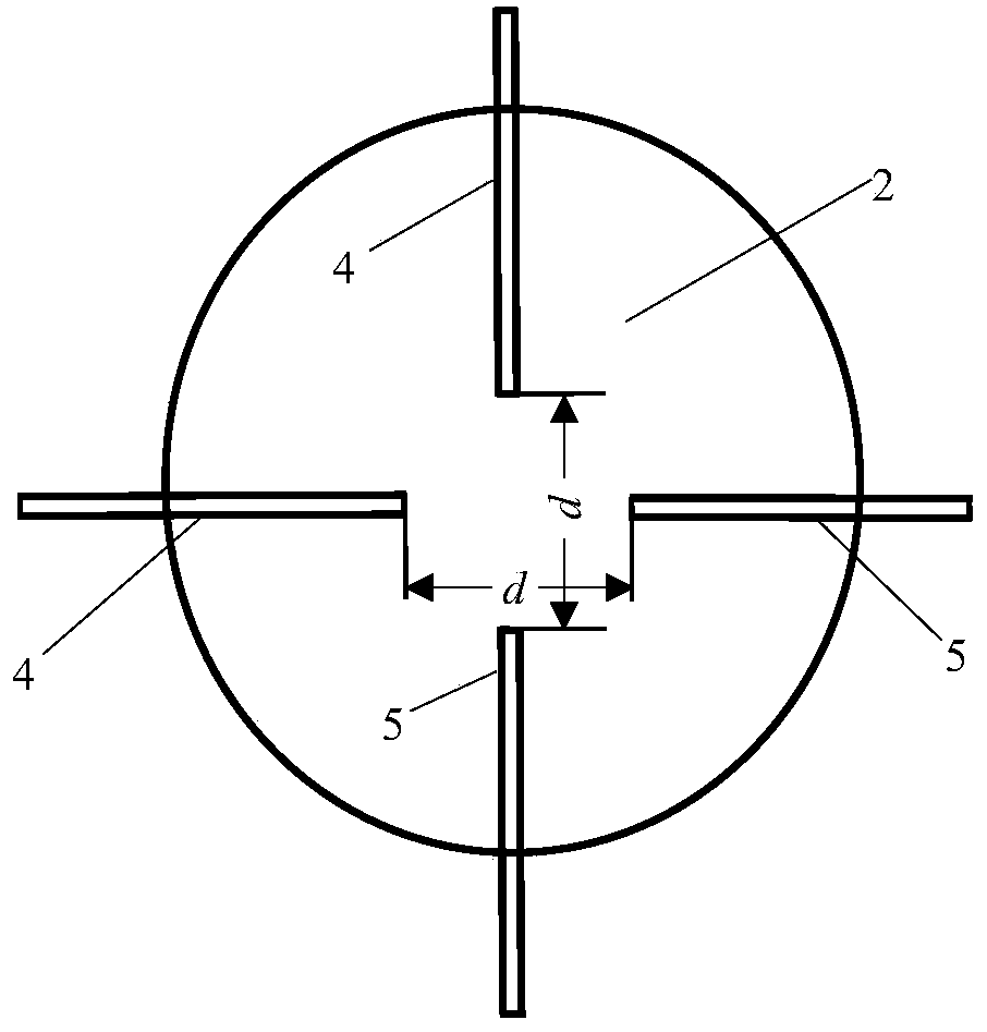
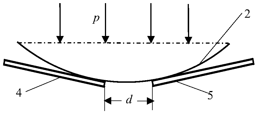
[0068] The structure of the optical fiber liquid level sensor is as follows: figure 1 As shown, it mainly consists of an elastic disc 2, a threaded cylinder 1 and two sections of optical fibers. From figure 1 It can be seen from the figure that two sections of the same optical fiber, the incident optical fiber 4 and the receiving optical fiber 5, are symmetrically pasted on the diameter of the elastic disc 2, and the distance is d, and the elastic disc 2 is pasted on the bottom of the threaded cylinder 1 , The outer wall of the threaded cylinder 1 is provided with threads. Such as figure 2 As shown, when the incident optical fiber and the receiving optical fiber are divided into two groups, the two incident optical fibers are distributed perpendicular to each other, and the two receiving optical fibers are distributed perpendicular to each other, which can avoid the incident when the optical fiber liquid level sensor is not placed horizontally in the liquid The vertical ac...


PUM


Abstract

The invention discloses an optical fiber liquid level sensor and a measuring method thereof. The optical fiber liquid level sensor comprises an elastic wafer, a threaded cylinder, an incident optical fiber and a receiving optical fiber, wherein the elastic wafer is stuck on the bottom part of the cylinder; the incident optical fiber and the receiving optical fiber are symmetrically stuck on the elastic wafer along the diameter direction; a gap is formed between the incident optical fiber and the receiving optical fiber. The optical fiber liquid level sensor and the measuring method have the beneficial effects that influence factors of liquid density variation and accelerated velocity on liquid level measurement can be eliminated, so that more accurate liquid level information is obtained. According to the optical fiber liquid level sensor, the liquid level information is measured in a non-contact manner, so that the measurement is not restricted by properties of to-be-measured liquid, the possibility of explosion risk caused by electric sparks generated due to electrical measurement is prevented, therefore the anti-explosion performance is realized; meanwhile, a sensing part is easily installed, the price is low, the situation that the sensing part of the optical fiber sensor is polluted by the liquid is prevented, the stability of the sensor in the measurement process is guaranteed to a certain extent, and the electromagnetic interference resistance performance is good.

Description

Technical field: [0001] The invention belongs to the technical field of sensors, in particular to an optical fiber liquid level sensor and a measuring method thereof. Background technique: [0002] At present, the research on optical fiber liquid level sensors mainly includes optical fiber microbending liquid level sensors, optical fiber F-P cavity liquid level sensors, and optical fiber grating liquid level sensors. The optical fiber microbend sensor needs to design movable teeth and fixed teeth. When under pressure, the elastic diaphragm drives the movable teeth to move towards the fixed teeth, causing the optical fiber to bend slightly. Its advantage is that the measurement accuracy is high, and the disadvantage is that the deformation teeth Difficult; the optical fiber F‐P cavity liquid level sensor is designed according to the principle of the F‐P cavity interferometer. The F‐P cavity is usually composed of an elastic diaphragm and an optical fiber end face. It has the ...

Claims


Application Information

Patent Timeline
Patent Type & Authority Patents(China)
IPC IPC(8): G01F23/292
Inventor 于春和王晓萌
Owner 河北微探科技有限公司
Why Eureka
Try Eureka