
RFID frequency conversion card reader and frequency sweeping and label reading method thereof

A card reader and label technology, applied in the field of card readers, can solve the problems of very little label information display, low data transmission rate, defects of ultra-high frequency label retroreflection characteristics, etc.

Active Publication Date: 2015-01-28
睿芯(大连)股份有限公司
View PDF3 Cites 6 Cited by
  • Summary
  • Abstract
  • Description
  • Claims
  • Application Information

AI Technical Summary

Problems solved by technology

[0003] However, for active tags, the working frequency required by active tags is generally UHF ultra-high frequency, and the corresponding tags also require high-frequency chips, so the cost of the product is relatively high; while for passive tags, Its operating frequency is around 13.56Mhz in the middle and high frequency range, and the data transmission rate is relatively low, or the ultra-high frequency is relatively concentrated in the 902-928MHz operating frequency band, the frequency is too high, and the known RFID card reader cannot efficiently identify it. Known RFID card readers can only display through sound and light and can only scan specific UHF frequencies, and rarely have the function of displaying tag information on mobile terminals
[0004] At the same time, the existing RFID tags basically work in the low frequency, mid-high frequency and ultra-high frequency bands, and both passive and active tags will have a chip in the tag to process information. Retroreflective characteristics have certain defects

Method used


Image

  • RFID frequency conversion card reader and frequency sweeping and label reading method thereof
  • RFID frequency conversion card reader and frequency sweeping and label reading method thereof
  • RFID frequency conversion card reader and frequency sweeping and label reading method thereof

Examples


Embodiment Construction

[0041] In order to make the object, technical solution and advantages of the present invention clearer, the present invention will be further described in detail below in conjunction with the accompanying drawings.

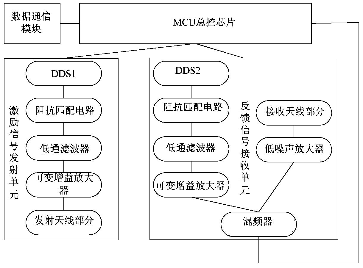
[0042] In order to change the problem that the existing RFID card reader can only display through sound and light and can only scan specific UHF frequencies, we have improved the circuit structure of the card reader so that it can not only read VHF (50M-500MHz) The frequency band tag can also transmit the information to the mobile terminal while reading the tag information, thereby displaying and storing product information.

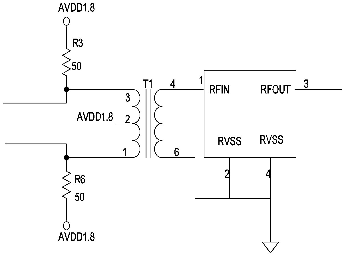
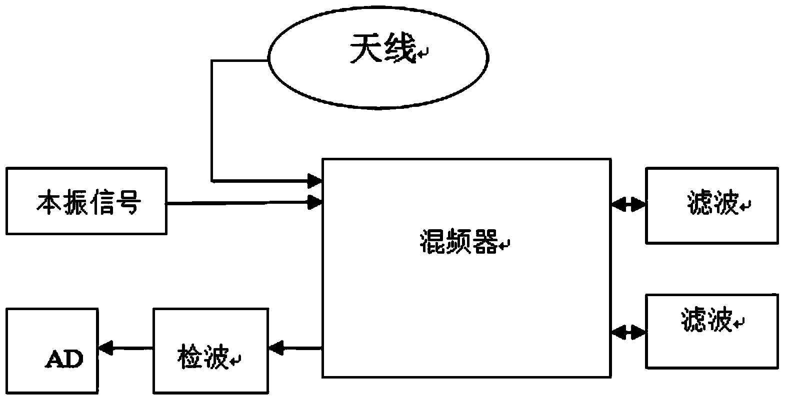
[0043] In view of this, if figure 1 — image 3 As shown, an RFID frequency conversion card reader is designed, which mainly includes an MCU master control chip, an excitation signal transmitting unit and a feedback signal receiving unit, and is used to send the tag information processed by the MCU master control chip to a mobile terminal fo...


PUM


Abstract

The invention discloses a RFID frequency conversion card reader and a frequency sweeping and label reading method of the RFID frequency conversion card reader. The card reader comprises an MCU master control chip, an excitation signal emission unit and a feedback signal receiving unit. The excitation signal emission unit comprises a direct digital synthesizer 1 (DDS1) connected with the MCU master control chip, an impedance matching circuit connected with the DDS1, a low-pass filter connected with the impedance matching circuit, a gain amplifier connected with the low-pass filter and a transmitting antenna part. The feedback signal receiving unit comprises a receiving antenna part, a differential signal source part, a mixer for receiving input signals and an intermediate frequency amplifier, wherein the differential signal source part is used for generating another path of mixer input signals, and the circuit structure generated by the input signals is the same as the circuit structure generated by signals of the excitation signal emission unit. By means of the novel RFID frequency conversion card reader, the labels of a VHF frequency band can be read, the information can be sent to a mobile terminal as well, and thus product information is stored and displayed.

Description

technical field [0001] The present invention relates to a card reader, in particular to an RFID tag reader that works in the VHF frequency band and is used to detect passive tags without chips, and transmits the detection results to mobile terminals through Bluetooth. The IPC international patent classification number is G06K 7 / 00. Background technique [0002] At present, the working principle of the known RFID card reader is that after the RFID tag enters the magnetic field, it receives the radio frequency signal sent by the reader, and sends out the product information stored in the chip by virtue of the energy obtained by the induced current, or actively sends a signal of a certain frequency After the reader reads and decodes the information, it sends it to the central information system for data processing, storage and display; correspondingly, it can be divided into passive tags and active tags. [0003] However, for active tags, the working frequency required by acti...

Claims


Application Information

Patent Timeline
Patent Type & Authority Applications(China)
IPC IPC(8): G06K7/00H04B5/00
Inventor 陈韦宁
Owner 睿芯(大连)股份有限公司
Learn More