A 4‑20ma current conversion circuit

A current conversion and circuit technology, applied in the direction of logic circuit connection/interface layout, etc., can solve the problems of poor potentiometer stability than resistance, inconvenient use, poor circuit stability, etc., to achieve simple circuit structure, easy implementation, and temperature drift. small effect

Inactive Publication Date: 2017-10-13
WUXI NUIST WEATHER SENSOR NETWORK TECH
View PDF6 Cites 0 Cited by
  • Summary
  • Abstract
  • Description
  • Claims
  • Application Information

AI Technical Summary

Problems solved by technology

[0002] In engineering, it is often necessary to convert voltage or PWM pulse to 4-20mA current. The current traditional implementation method is as follows: 1. The conversion is realized through the special conversion chip XTR110 or XTR115 introduced by Burr-Brown Company. However, the cost of XTR110 or XTR115 is high. Moreover, XTR110 is complicated to adjust. Although XTR115 does not need to be adjusted, it is easy to use, but it is inconvenient to use in occasions that require lower reference voltage or three-wire work.
Second, through figure 1 The conversion circuit shown realizes conversion, but the circuit has the following disadvantages: (1), 4 and 20mA need to be adjusted separately and are involved with each other, and the adjustment cannot be completed at one time; (2), resistors R1 and R2 need to be paired, which is inconvenient; ( 3) Because the stability of the potentiometer is worse than the resistance, the stability of the circuit is relatively poor; (4) There is a risk of overcurrent, and current limiting measures must be taken; (5) The cost of materials and labor is high

Method used


Image

  • A 4‑20ma current conversion circuit
  • A 4‑20ma current conversion circuit

Examples


Embodiment Construction

[0011] The present invention will be further described below in conjunction with drawings and embodiments. It should be understood that the specific embodiments described here are only used to explain the present invention, but not to limit the present invention. In addition, it should be noted that, for the convenience of description, only parts related to the present invention are shown in the drawings but not all content. Unless otherwise defined, all technical and scientific terms used herein have the same meaning as commonly understood by one of ordinary skill in the technical field of the invention. The terms used herein in the description of the present invention are for the purpose of describing specific embodiments only, and are not intended to limit the present invention. As used herein, the term "and / or" includes any and all combinations of one or more of the associated listed items.

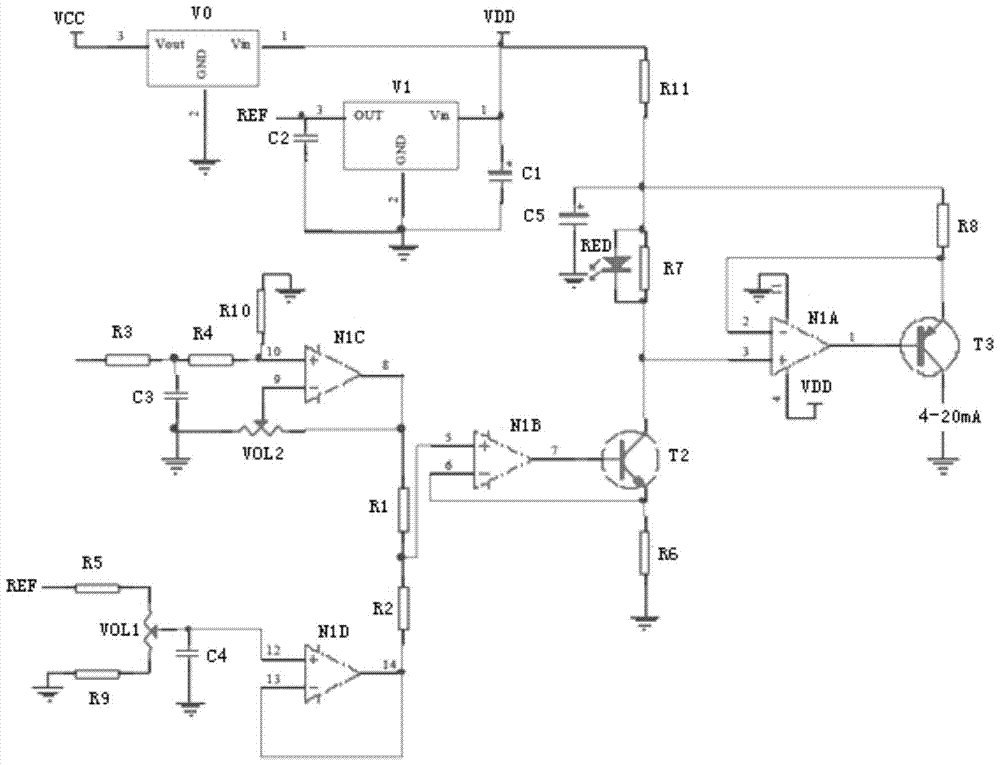
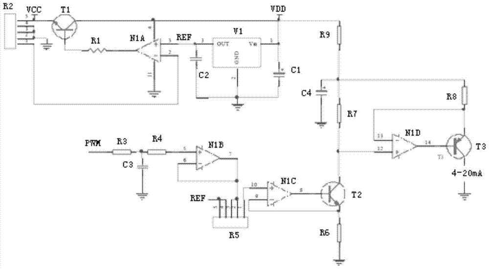
[0012] Please refer to figure 2 as shown, figure 2 The structure diagram of...


PUM


Abstract

The invention discloses a 4-20mA current conversion circuit, comprising: a resistor R1, an NPN bipolar transistor T1, a resistor R2, an operational amplifier N1A, a reference voltage source V1, a capacitor C1, a capacitor C2, a resistor R3, a capacitor C3, and a resistor R4 , operational amplifier N1B, resistor R5, operational amplifier N1C, NPN bipolar transistor T2, resistor R6, resistor R7, capacitor C4, resistor R8, resistor R9, operational amplifier N1D and PNP bipolar transistor T3. The invention not only has simple circuit structure, low cost, and is easy to realize, but also has small temperature drift, and has an overcurrent protection function. When there is no adjustment, the conversion error is 0.5%-1%. Fine-tuning the resistance value of resistor R6 can reduce the error to 0.05%.

Description

technical field [0001] The invention relates to a conversion circuit, in particular to a 4-20mA current conversion circuit. Background technique [0002] In engineering, it is often necessary to convert voltage or PWM pulse to 4-20mA current. The current traditional implementation method is as follows: 1. The conversion is realized through the special conversion chip XTR110 or XTR115 introduced by Burr-Brown Company. However, the cost of XTR110 or XTR115 is high. Moreover, XTR110 is complicated to adjust. Although XTR115 does not need adjustment and is easy to use, it is inconvenient to use in occasions that require lower reference voltage or three-wire operation. Second, through figure 1 The conversion circuit shown realizes conversion, but the circuit has the following disadvantages: (1), 4 and 20mA need to be adjusted separately and are involved with each other, and the adjustment cannot be completed at one time; (2), resistors R1 and R2 need to be paired, which is incon...

Claims


Application Information

Patent Timeline
Patent Type & Authority Patents(China)
IPC IPC(8): H03K19/0175
Inventor 李月明禹胜林
Owner WUXI NUIST WEATHER SENSOR NETWORK TECH
Why Eureka
Try Eureka