Steering gear

A technology of steering mechanism and deflection shaft, which is applied in steering mechanism, power steering mechanism, electric steering mechanism, etc., and can solve problems such as different steering performance

Active Publication Date: 2015-01-28
ROBERT BOSCH AUTOMOTIVE STEERING
View PDF5 Cites 7 Cited by
  • Summary
  • Abstract
  • Description
  • Claims
  • Application Information

AI Technical Summary

Problems solved by technology

[0009] A disadvantage of the bearing concepts known from the prior art for achieving backlash-free meshing of the pinion and gear wheel is that different steering behaviors can be felt when turning the steering column to the left or to the right.

Method used


Image

  • Steering gear
  • Steering gear
  • Steering gear

Examples


Embodiment Construction

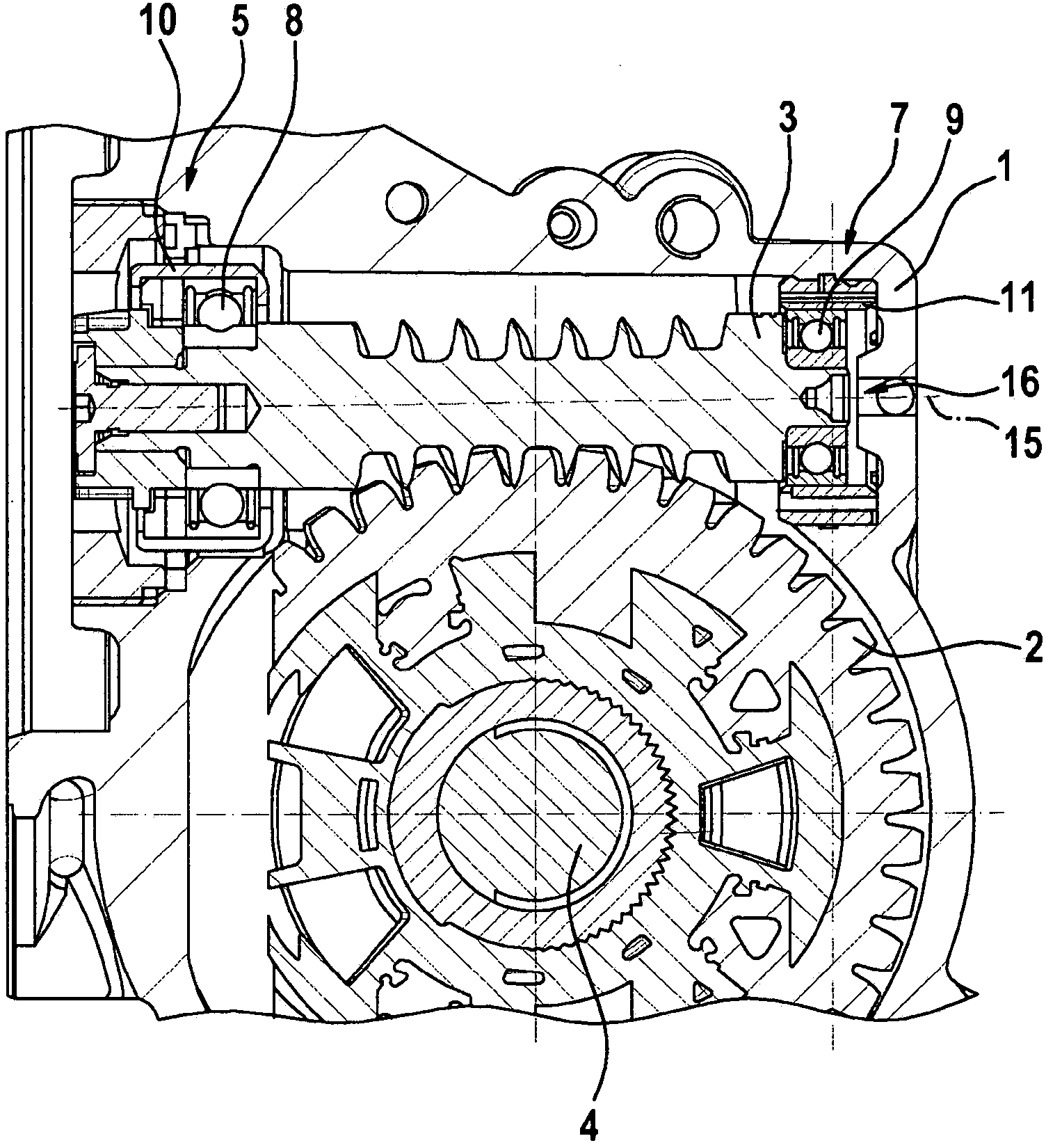
[0034] figure 1 The main components of an embodiment of the steering gear according to the invention are shown. The steering mechanism comprises a housing 1 in which a gear 2 and a pinion 3 meshing with the gear 2 are mounted. The pinion 3 and the pinion shaft containing the pinion are formed integrally in the form of a worm.

[0035] The gear 2 is fixed firmly on the steering column 4 of the car.

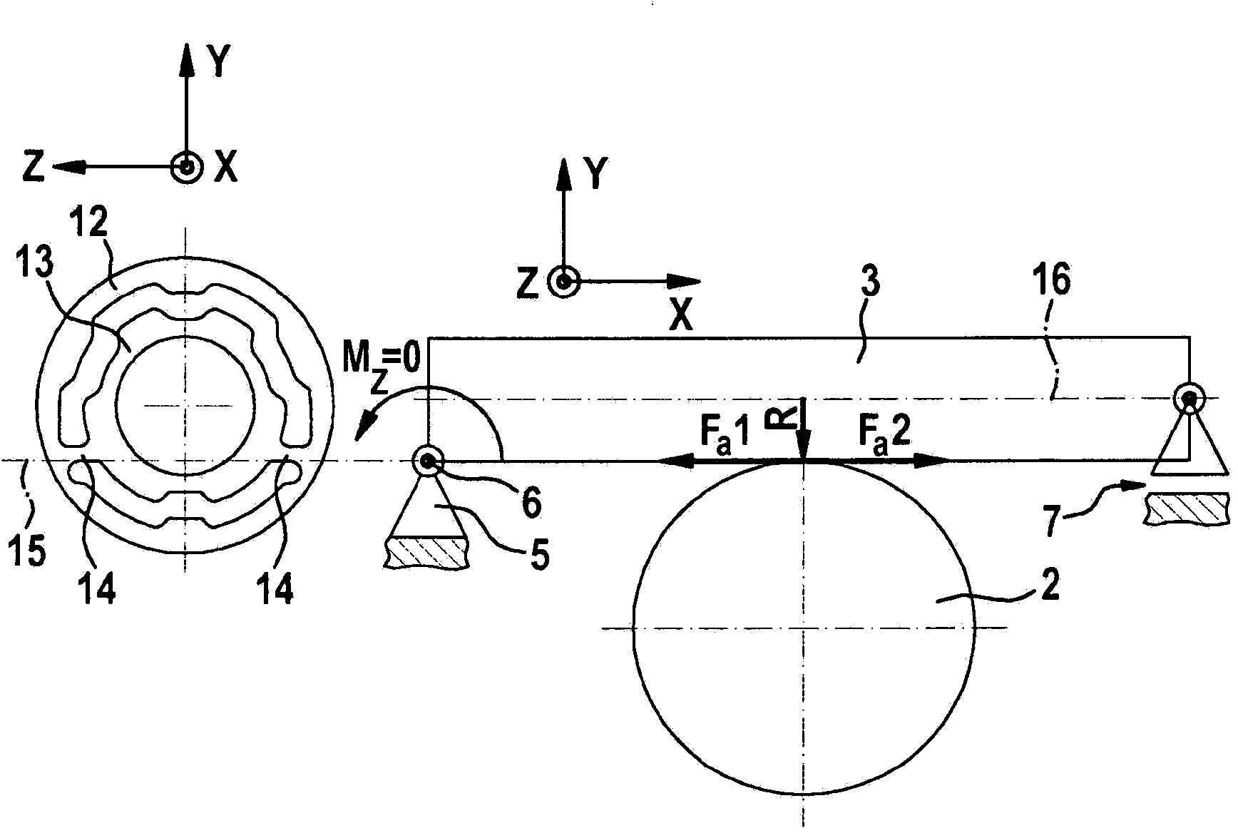
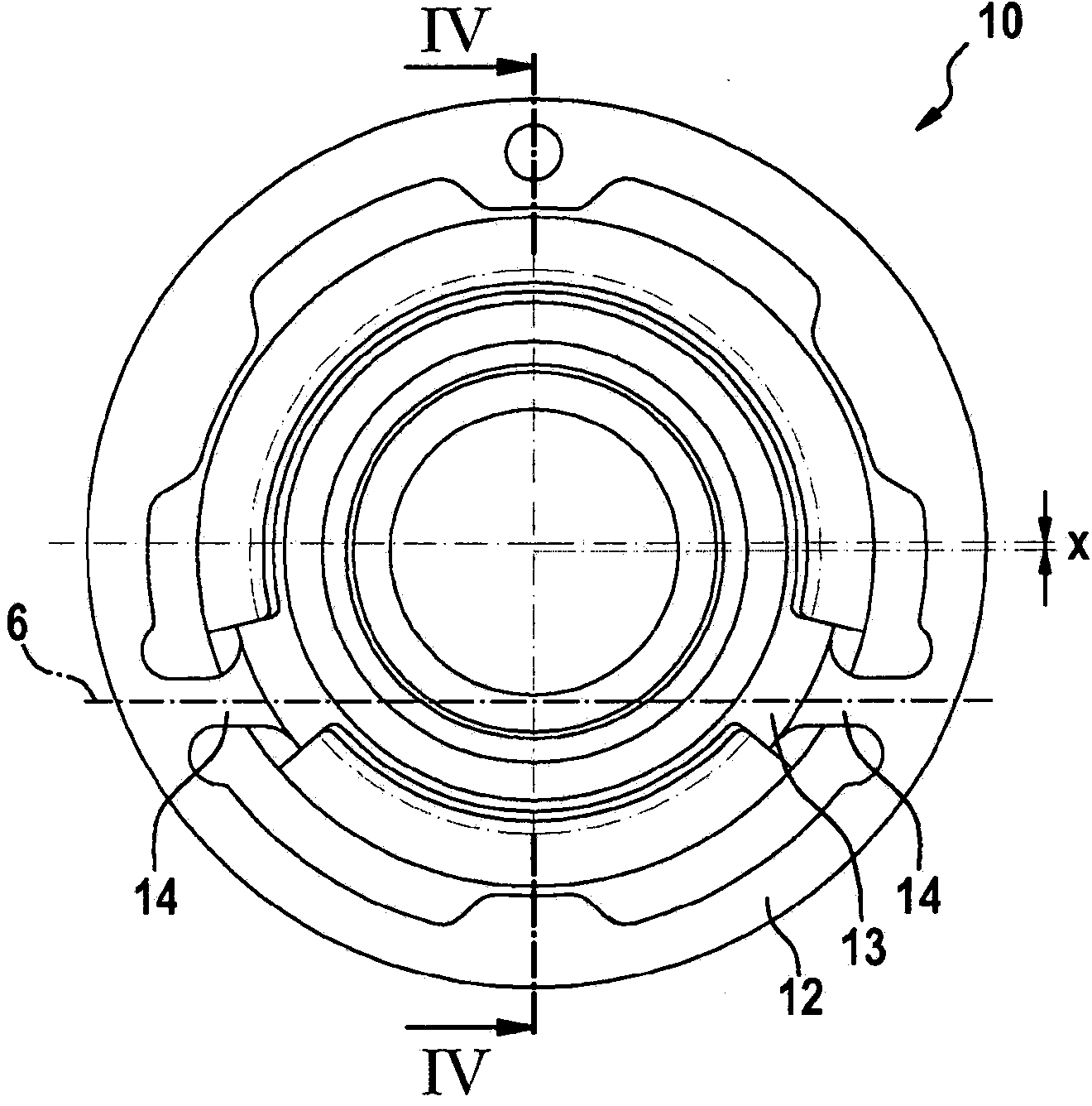
[0036] The pinion 3 has a drive-side end via which the pinion can be connected to an output shaft of a drive (not shown), for example an electric motor. In the region of this end on the drive side, the pinion 3 is mounted in the housing by means of a first bearing. This bearing is designed as a fixed bearing 5 , which essentially does not allow translation of the pinion 3 relative to the housing 1 , but permits a deflection about the deflection axis 6 .

[0037] This deflection causes a deflection of the free end of the end opposite the drive side of the pinion 3 , where the pi...


PUM


Abstract

A steering gear having a gearwheel (2), having a pinion (3) which meshes with said gearwheel and having a pinion shaft which comprises the pinion (3) and which is mounted so as to be pivotable about a pivot axis (6) perpendicular to the longitudinal axis (16) of the pinion shaft is characterized in that the radial spacing between the pivot axis (6) and the location of toothed engagement (15) between the gearwheel (2) and pinion is smaller than the core radius of the pinion (3).

Description

technical field [0001] The invention relates to a steering mechanism and in particular to a steering mechanism for a power steering system of an automobile. Background technique [0002] A power steering system is installed in conventional motor vehicles, which generates an assist torque during steering and thus reduces the steering torque exerted by the driver on the steering column. [0003] Such known power steering systems are based on a steering mechanism which converts the transmission power of a hydraulic or electric drive and transmits it to the steering column. Such steering mechanisms are often formed in the form of a helical roller drive and in particular as a helical gear or worm gear, that is to say they comprise a gear (which is directly or indirectly connected to the steering rod) and a drive via a A pinion driven by a pinion shaft. [0004] What is problematic is the gear play that occurs in such steering gears, which is formed due to component tolerances, ...

Claims


Application Information

Patent Timeline
Patent Type & Authority Applications(China)
IPC IPC(8): B62D5/04F16H57/021
CPCF16H2057/127F16H2057/0222F16H57/039B62D5/0409F16H2057/0213Y10T74/188F16H55/24Y10T74/19828Y10T74/19623B62D5/0454F16H57/12B62D3/04F16C2380/27B62D3/02F16H19/02
Inventor J·哈费尔马尔茨D·菲克泽尔
Owner ROBERT BOSCH AUTOMOTIVE STEERING
Why Eureka
Try Eureka