3D (three dimensional) printing process with laser beam scanning in archimedes spiral way

An Archimedes spiral, 3D printing technology, applied in the field of 3D printing technology, can solve the problems of affecting the scanning effect, reducing the deflection angle, application difficulties, etc., to improve the printing quality, reduce the relative size and reduce the cost. Effect

Inactive Publication Date: 2015-02-04
康子纯
View PDF6 Cites 9 Cited by
  • Summary
  • Abstract
  • Description
  • Claims
  • Application Information

AI Technical Summary

Problems solved by technology

[0002] At present, several mainstream 3D printing processes that use laser beam printing, such as SLA, SLS, SLM, LOM, etc., whether they use the scanning method before the objective lens or the scanning method after the objective lens, can obtain high High-precision scanning effect, the scanning point on the working surface has a small and consistent size, or the defocus error is small within the depth of focus; however, when scanning a large working surface, if the front scanning method of the objective lens is used , because the flat field lens (F-Theta lens) with a larger working area is expensive to manufacture, and the focal length is longer, the application is difficult, the focal plane glazing class be

Method used


Image

  • 3D (three dimensional) printing process with laser beam scanning in archimedes spiral way
  • 3D (three dimensional) printing process with laser beam scanning in archimedes spiral way
  • 3D (three dimensional) printing process with laser beam scanning in archimedes spiral way

Examples


Embodiment 1

[0021] Embodiment 1: the whole machine adopts the present invention that 3 lasers are mounted on the laser disc of the turntable;

Embodiment 2

[0022] Embodiment 2: The whole machine adopts the present invention in which three lasers are mounted on the turntable guide rail guide frame;

Embodiment 3

[0023] Embodiment 3: The whole machine adopts the present invention that a single laser is set independently from the turntable;

[0024] Example 1:

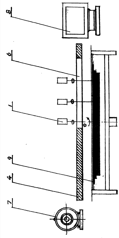
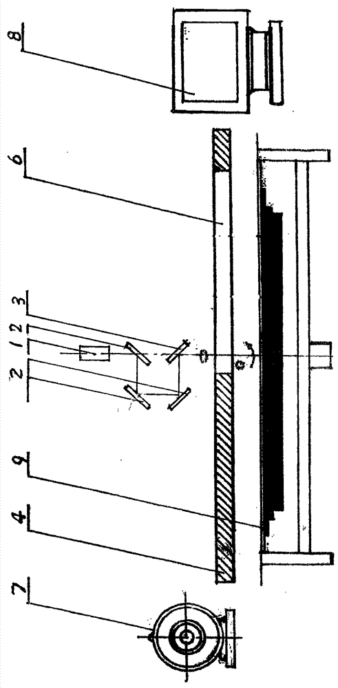
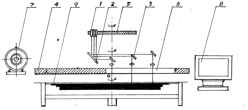
[0025] The whole machine adopts the Archimedes line scanning 3D printing process ( figure 1), including: laser (1) and optical path system (2, 3), turntable (4) and guide rail (11) guide frame (13) system, spindle motor (7) and guide frame translational servo motor (10, 12) system , computer (8) control system. Said laser (1) and optical path system (2, 3) are characterized in that three lasers (1) are arranged in a straight line and eccentrically installed on the laser disk (5) of the turntable (4), and the laser beam (1) is then Eccentrically introduced into the optical path system (2, 3) on the turntable (4), the laser beam is reflected by the fixed mirror (2) on the turntable (4), and enters the translational guide frame (13) on the guide rail (1) in sequence The three reflectors (3) of each reflector (3) are reflected an...


PUM


Abstract

A 3D (three dimensional) printing process with laser beam scanning in archimedes spiral way comprises a laser and optical system, a turntable and guide rail guide frame system, a spindle motor and guide frame shift servo motor system, and a computer control system. A laser is mounted on a turntable laser disc or a turntable guide frame, or is mounted independently from a turntable, a laser beam is focused onto a printer working plane by a stationary reflector of turntable optical system and a reflector and a lens on the guide frame, or, a laser beam of a laser on the guide frame is focused onto the printer working plane by the lens; when the turntable is driven by a spindle motor to rotate in local constant angular velocity or constant angular velocity, and the guide frame is driven by a servo motor to move horizontally in constant velocity, omission-free and no-repeat archimedes spiral scanning of the laser beam on SLA, SLS, SLM and LOM printing working planes can be completed, and after layer-by-layer processing, a workpiece body is obtained. The printing process can realize no-distortion and high quality scanning of ultra large working planes and processing of ultra large workpieces, has the advantages of simple structure, low cost and excellent quality, is especially suitable for printing aerospace, aviation, electric power, marine, construction and other large complex workpieces.

Description

Technical field: [0001] The present invention relates to 3D printing technology. Background technique: [0002] At present, several mainstream 3D printing processes that use laser beam printing, such as SLA, SLS, SLM, LOM, etc., whether they use the scanning method before the objective lens or the scanning method after the objective lens, can obtain high High-precision scanning effect, the scanning point on the working surface has a small and consistent size, or the defocus error is small within the depth of focus; however, when scanning a large working surface, if the front scanning method of the objective lens is used , because the flat field lens (F-Theta lens) with a larger working area is expensive to manufacture, and the focal length is longer, the application is difficult, the focal plane glazing class becomes larger, and the scanning pattern distortion on the working surface becomes larger, which affects the scanning effect ; If the objective lens rear scanning meth...

Claims


Application Information

Patent Timeline
IPC IPC(8): B29C67/00
Inventor 康子纯
Owner 康子纯
Why Eureka
Try Eureka