A system for strengthening post-denitrification denitrification process

A post-denitrification and denitrification technology, applied in the field of water treatment, can solve the problems of low denitrification efficiency, low operation and treatment efficiency, and difficulty in further improvement, etc. Handling effects with stable effects

Inactive Publication Date: 2017-04-12
NANJING INST OF ENVIRONMENTAL SCI MINIST OF ECOLOGY & ENVIRONMENT OF THE PEOPLES REPUBLIC OF CHINA
View PDF6 Cites 0 Cited by
  • Summary
  • Abstract
  • Description
  • Claims
  • Application Information

AI Technical Summary

Problems solved by technology

[0009] However, the existing post-denitrification denitrification process has problems such as insufficient carbon source in the denitrification process, the overall process denitrification efficiency is relatively low, and it is difficult to further improve, and the operation and treatment efficiency is low under low temperature conditions in winter.

Method used


Image

  • A system for strengthening post-denitrification denitrification process
  • A system for strengthening post-denitrification denitrification process
  • A system for strengthening post-denitrification denitrification process

Examples


Embodiment 1

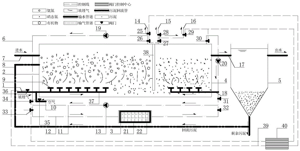
[0087] This embodiment is based on the above-mentioned technical scheme, and the waste water is treated, and the influent water quality of a city sewage is BOD 5 : 240-330mg / L, NH 3 -N: 34-43mg / L, TN: 42-55mg / L, daily processing capacity 3000m 3 / d.

[0088] IN pool 2 length × width × height: 30m × 10m × 3.5m effective height 3m, ID pool 4 length × width × height: 10m × 10m × 3.5m effective height 3m, the distance between the partition wall 38 and the pool bottom is 0.6 of the pool height m; the IN tank aeration pipe 37 in the IN tank 2 of the enhanced nitrification tank extends 20 m into the tank; the average gas supply volume of the landfill gas inlet pipe 1 in the pre-acclimation and treatment stages of the IN tank 2 is 680 m 3 / h, wherein the mixing ratio of landfill gas and air is 2:1, the proportion of gas circulating in the IN pool gas internal circulation pipe 6 is 50%, and the hydraulic retention time is 9.6h; The average gas supply volume of buried gas intake pipe...

Embodiment 2

[0090] In this embodiment, based on the above technical scheme, a certain livestock and poultry wastewater is treated, and the average water quality is COD Cr 2530mg / L, TN640mg / L, NH4 + -N280mg / L, daily processing capacity 5000m 3 / d.

[0091] IN pool 2 length × width × height: 30m × 10m × 3.5m effective height 3m, ID pool 4 length × width × height: 10m × 10m × 3.5m effective height 3m, the distance between the partition wall 38 and the pool bottom is 0.6 of the pool height m; the aeration pipe 37 of the IN tank in the IN tank 2 of the enhanced nitrification tank extends 20 m into the tank; the average gas supply volume of the landfill gas inlet pipe 1 in the pre-acclimation and treatment stages of the IN tank 2 is 900 m 3 / h, wherein the mixing ratio of landfill gas and air is 2:1, the proportion of gas circulating in the IN tank gas internal circulation pipe 6 is 80%, and the hydraulic retention time is 5.76h; The average gas supply volume of buried gas intake pipe 1 is 3...


PUM

PropertyMeasurementUnit
thicknessaaaaaaaaaa

Abstract

The present invention discloses a system for strengthening a post-denitrification denitrogenation process. The system comprises a landfill gas inlet pipe, a nitrification strengthening tank (IN tank), a deaerator, a denitrification strengthening tank (ID tank) and a sedimentation tank, wherein the IN tank adopts landfill gas to aerate, the ID tank adopts the landfill gas with the oxygen removed by the deaerator to aerate, the length of the IN tank aeration pipe extending into the IN tank is 2 / 3 of the length of the tank, the IN tank and the ID tank are separated by a separation wall, the distance between the separation wall and the tank bottom is 1 / 5 of the height of the tank, the mixed ratio of the landfill gas to the air in the IN tank is 2:1-4:1, the internally circulated gas ratio in the IN tank is 50-80%, the internally circulated gas ratio in the ID tank is 70-90%, and the pre-acclimatization times of the microorganisms in the IN tank and the ID tank are 3-5 d. The system of the present invention has characteristics of high denitrogenation efficiency, stable treatment effect, simple process, less treatment structure and equipment, low infrastructure construction and operation cost, and the like.

Description

technical field [0001] The invention relates to a system for enhancing biological action efficiency in the technical field of water treatment, more specifically, a system (IN-ID system) for strengthening post denitrification and denitrification. Background technique [0002] Post-denitrification denitrification process is also called single-stage biological denitrification process (such as figure 1 shown). The removal of organic pollutants, the ammonification process and the nitrification reaction are carried out in the same reactor (aeration tank), and the mixed liquid flowing out from the reactor directly enters the anoxic tank for denitrification without precipitation. The process flow is simple, the processing structures and equipment are less, and the common shortcomings of the multi-stage biological denitrification system are overcome. However, there are still inherent shortcomings of post-denitrification, that is, the alkalinity of the nitrification process may be i...

Claims


Application Information

Patent Timeline
Patent Type & Authority Patents(China)
IPC IPC(8): C02F3/30C02F3/34
Inventor 吴睿彭禹洪超陈丹杨昉婧李道进沈明霞
Owner NANJING INST OF ENVIRONMENTAL SCI MINIST OF ECOLOGY & ENVIRONMENT OF THE PEOPLES REPUBLIC OF CHINA
Why Eureka
Try Eureka