Walking-beam-free type intelligent oil pumping unit

A beamless pumping unit technology, applied in the direction of production fluid, wellbore/well components, earthwork drilling and production, etc., can solve the problem of not being able to adapt to the balance state of the pumping unit, destroying the balance state of the pumping unit, requiring maintenance and deceleration problems such as equipment, to achieve the effect of improving workover operation speed, light weight and simple structure

Inactive Publication Date: 2015-02-04
DAQING DANNUO PETROLEUM TECH DEV
View PDF6 Cites 9 Cited by
  • Summary
  • Abstract
  • Description
  • Claims
  • Application Information

AI Technical Summary

Problems solved by technology

[0002] At present, the mechanical balance of the pumping unit is mainly realized by the counterweight of the balance weight. During the downstroke, the potential energy of the balance weight is increased to store energy, and during the upstroke, the potential energy of the balance weight is released to release energy. Taking the pumping unit as an example, the weight of the sucker rod and the liquid column load on the cross-sectional area of ​​the piston are balanced by increasing or decreasing the weight of the beam balance weight. All will destroy the original balance state of the pumping unit, the above-mentioned balance counterweight can only be a passive counterweight, and cannot adapt to the balance state of the dynamic change of the pumping unit, and there are problems of low mechanical efficiency and inconvenient maintenance
Low mechanical transmission efficiency, power consumption, large mechanical impact; need to maintain the reducer; mechanical transmission is a chain, mechanical maintenance is difficult, and the mechanical failure rate is high

Method used


Image

  • Walking-beam-free type intelligent oil pumping unit
  • Walking-beam-free type intelligent oil pumping unit
  • Walking-beam-free type intelligent oil pumping unit

Examples


Embodiment Construction

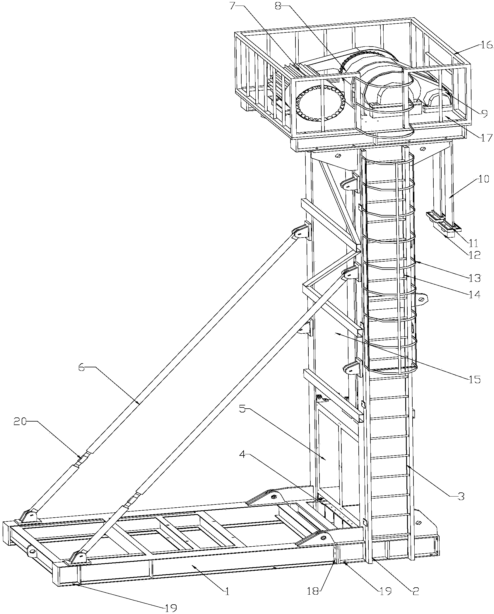
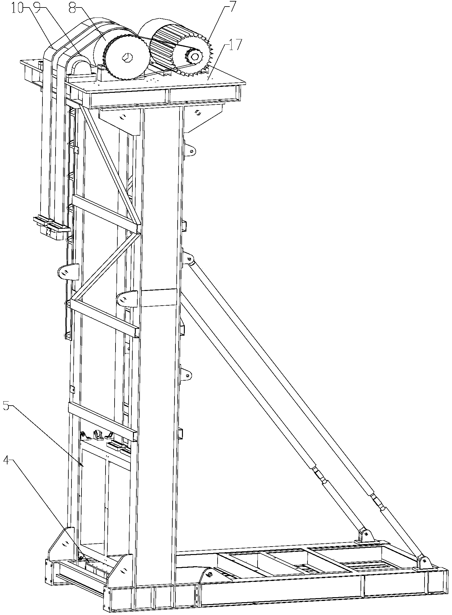
[0010] The present invention will be further described below in conjunction with accompanying drawing:

[0011] Depend on figure 1 combine figure 2 As shown, the beamless intelligent pumping unit includes a fixed base 1 and a movable base 2, the fixed base 1 and the movable base 2 are connected through a pin-type joint connection and fastening bolts 18, and the upper part of the movable base 2 is fixedly connected to the frame 3 , the frame 3 is a steel bracket structure, the upper end of the frame 3 is hinged with the fixed base 1 through a pull rod 6, the upper end of the frame 3 is provided with a platform 17, and a permanent magnet motor 7 is installed on the platform 17, and the permanent magnet motor 7 and the driving roller 8 Connected by chain transmission, the drive roller 8 is equipped with a guide roller 9 parallel to the axis of the drive roller 8 near the edge of the platform 17, and the drive roller 8 is provided with a long hole near the platform 17 of the per...


PUM


Abstract

The invention provides a walking-beam-free type intelligent oil pumping unit. A machine frame is of a steel bracket structure; the upper end of the machine frame is connected with a fixed base through a pull rod hinge; a permanent magnet motor, a driving roller and a guide roller are mounted on a platform on the machine frame; a belt bypasses the driving roller and the guide roller, extends downwards vertically and is fixedly connected with a belt clamp and a beam hanger; the other end of the belt is connected with a weight box; a buffer is arranged on a movable base. The permanent magnet motor directly drives the driving roller to rotate so as to drive the belt to move up and down, and low-mechanical-efficiency complicated structures such as a crank arm balance block and belt wheel transmission of a conventional oil pumping unit are replaced; the belt rectilinearly moves up and down to lift an oil pumping rod, so that the phenomenon of eccentric wear between the oil pumping rod and a wellhead is avoided, the service life of the oil pumping rod is prolonged, the workover operation speed is increased by virtue of an adjustable removal mechanism, the labor intensity of the workover operation is alleviated, and the whole oil pumping unit has the characteristics of simple structure, less movement parts, less transmission chains, high mechanical efficiency, low energy consumption, simplicity in maintenance and reliability in operation.

Description

Technical field: [0001] The invention relates to the field of petroleum production equipment, in particular to a beamless intelligent pumping unit. Background technique: [0002] At present, the mechanical balance of the pumping unit is mainly realized by the counterweight of the balance weight. During the downstroke, the potential energy of the balance weight is increased to store energy, and during the upstroke, the potential energy of the balance weight is released to release energy. Taking the pumping unit as an example, the weight of the sucker rod and the liquid column load on the cross-sectional area of ​​the piston are balanced by increasing or decreasing the weight of the beam balance weight. All can destroy the original balance state of the pumping unit, and the above-mentioned balance counterweight can only be a passive counterweight, and cannot adapt to the balance state of the dynamic change of the pumping unit, and has the problems of low mechanical efficiency ...

Claims


Application Information

Patent Timeline
Patent Type & Authority Applications(China)
IPC IPC(8): E21B43/00
CPCE21B43/00
Inventor 苏志深李鸽
Owner DAQING DANNUO PETROLEUM TECH DEV
Why Eureka
Try Eureka