
Free piston engine

A piston engine, free technology, used in free piston engines, machines/engines, mechanical equipment, etc., can solve problems such as pressure reduction, change, and reduction, and achieve the effect of collision prevention and pressure stability

Active Publication Date: 2015-02-04
HUAQIAO UNIVERSITY
View PDF6 Cites 23 Cited by
  • Summary
  • Abstract
  • Description
  • Claims
  • Application Information

AI Technical Summary

Problems solved by technology

At present, the hydraulic oil output from the compression accumulator to the compression chamber is generally connected directly to the compression chamber by the compression accumulator. Due to the movement of the piston assembly, the volume of the compression chamber gradually increases, so the compression accumulator needs to be continuously supplied. The compression chamber is supplied with oil, so the pressure of the compression accumulator is reduced, and the pressure of the hydraulic oil flowing into the compression chamber is correspondingly reduced; although in the subsequent expansion stroke, the hydraulic oil in the compression chamber flows back to the compression accumulator However, due to losses such as leakage in the middle, the pressure in the compression accumulator gradually decreases, and the pressure in each cycle cannot be guaranteed to be equal, so the compression process of the engine changes in each cycle

Method used


Image

  • Free piston engine

Examples


Embodiment Construction

[0040] The present invention will be further described below in conjunction with the accompanying drawings and specific embodiments.

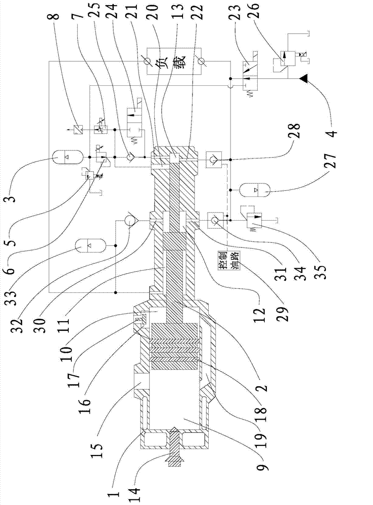
[0041] Such as figure 1 As shown, the free piston engine provided by this embodiment includes a cylinder block 1, a piston assembly 2, a compression accumulator 3 and a pumping station 4, and also includes a first proportional overflow valve 5, a proportional pressure reducing valve 6, a proportional speed regulation Valve 7 and pressure sensor 8. Of course, the free-piston engine of this embodiment also needs a control system. In this embodiment, the control system adopts the control system adopted by the existing free-piston engine. The speed regulating valve 7, the pressure sensor 8 and other components and the connection methods of the original components mentioned below are all conventional connection methods, which will not be described in detail here and below.

[0042] The piston assembly 2 is arranged in the piston chamber of the cy...


PUM


Abstract

The invention provides a free piston engine, which comprises a cylinder block, a compression accumulator, a pump station and a piston assembly, and also comprises a first proportional overflow valve, a proportional pressure reducing valve, a proportional velocity regulating valve and a pressure sensor; a piston chamber in the cylinder block is divided into a combustion chamber, an air intake chamber, a balance chamber, a pump chamber and a compression chamber by the piston assembly. As a pipeline connected with two inlets of a compression main port and a compression starting port of the compression chamber and the compression accumulator is provided with the proportional pressure reducing valve, the proportional velocity regulating valve, a reversing valve, the proportional overflow valve and the pressure sensor, according to the detection signal of the pressure sensor connected with the compression accumulator, the reversing valve is switched between the compression accumulator and an oil supply accumulator, and therefore oil supply work on high and low-pressure two oil lines is completed by utilizing one hydraulic pump station; moreover, after hydraulic oil in the compression accumulator flows through the proportional pressure reducing valve, stable pressure can be obtained and supplied for the compression chamber, so that the pressure of the inlet of the compression chamber is stable.

Description

technical field [0001] The invention relates to an engine, in particular to a free piston engine with stable inlet pressure of a compression chamber. Background technique [0002] With the development of the global economy, the consumption of energy has intensified, and the resulting environmental problems have become increasingly prominent. Energy saving and environmental protection have become two major issues of global concern. The hydraulic free piston engine has a variable compression ratio and can achieve Flexible arrangement, which can improve fuel economy and reduce emission pollution, is a promising power star for walking machinery. [0003] At present, the hydraulic free piston engine is still in the laboratory prototype test stage, and there are many key technologies and problems to be solved, among which the precise control of the compression ratio is the most important point. For a single-piston hydraulic free-piston engine, the impact on its compression ratio ...

Claims


Application Information

Patent Timeline
Patent Type & Authority Applications(China)
IPC IPC(8): F02B71/04F15B1/02
Inventor 任好玲林添良付胜杰杨帆叶月影
Owner HUAQIAO UNIVERSITY
Learn More