Low-concentration gas wet pressurization equipment and method of coal mine

A low-concentration gas and pressurization equipment technology, which is applied in the direction of mechanical equipment, pipeline systems, gas/liquid distribution and storage, etc., can solve the problems that it cannot be pressurized, and it is difficult to meet the requirements of ensuring the inlet pressure of the generator set, so as to achieve safety Complete measures, low cost, to ensure the effect of import pressure

Inactive Publication Date: 2015-02-04
北京扬德环保能源科技股份有限公司
View PDF1 Cites 6 Cited by
  • Summary
  • Abstract
  • Description
  • Claims
  • Application Information

AI Technical Summary

Problems solved by technology

[0004] The technical problem to be solved by the present invention is to provide a low-concentration gas wet pressurization device and method to overcome the defects in the prior art that the low-concentration gas cannot be pressurized during the transportation process, and it is difficult to meet the requirements of ensuring the inlet pressure of the generator set

Method used


Image

  • Low-concentration gas wet pressurization equipment and method of coal mine

Examples


Embodiment 1

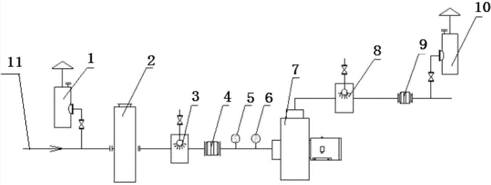
[0035] A low-concentration gas wet pressurization method of the present invention comprises the following steps:

[0036] 1. The gas with a concentration of 15% is transported from the gas drainage station along the main gas pipeline, flows in from the air inlet of the first wet pressure relief and explosion relief device, flows out from the gas outlet, and is transported to the water through the main pipeline. The air inlet of the sealed flame arrester flows out from the air outlet of the water sealed flame arrester;

[0037] 2. The low-concentration gas flowing out of the gas outlet of the water-sealed flame arrester is transported to the first spraying device through the main pipeline, and the low-concentration gas is dedusted and fire-stopped by the fine water mist sprayed from the first spraying device;

[0038] 3. After passing through the first spraying device, the gas is transported to the steam-water separator through the main pipeline, and the free water in the low-c...

Embodiment 2

[0043] A low-concentration gas wet pressurization method of the present invention comprises the following steps:

[0044]1. The gas with a concentration of 21% is transported from the gas drainage station along the main gas pipeline, flows in from the air inlet of the first wet pressure relief and explosion relief device, flows out from the gas outlet, and is transported to the water through the main pipeline. The air inlet of the sealed flame arrester flows out from the air outlet of the water sealed flame arrester;

[0045] 2. The low-concentration gas flowing out of the gas outlet of the water-sealed flame arrester is transported to the first spraying device through the main pipeline, and the low-concentration gas is dedusted and fire-stopped by the fine water mist sprayed from the first spraying device;

[0046] 3. After passing through the first spraying device, the gas is transported to the steam-water separator through the main pipeline, and the free water in the low-co...


PUM


Abstract

The invention relates to low-concentration gas wet pressurization equipment. The equipment comprises a gas delivery main pipeline, wherein the gas delivery main pipeline is provided with a first wet pressure relief and explosion venting device, a water seal flame arrester, a first spray device, a steam-water separator, a flow measurement device, a pressure and temperature measurement device, a centrifugal booster fan, a second spray device, a dry flame arrester and a second wet pressure relief and explosion venting device from an air flow direction in sequence. Since the series of devices are rationally arranged on the low-concentration gas delivery main pipeline to meet the requirement on pressurization in the low-concentration gas delivery process to achieve the purpose of guaranteeing the inlet pressure of a generating set, and the equipment cost is lower compared with the existing water circulating vacuum pump, the equipment is easy to mount, the safety precautions are complete, and the purpose of low-concentration gas pressurization can be achieved.

Description

technical field [0001] The invention relates to a coal mine low-concentration gas wet pressurization device and method, belonging to the field of low-concentration gas transportation safety. Background technique [0002] In the previous design of coal mine gas drainage system, the gas was directly emptied near the drainage station after being pumped out of the roadway, so the outlet pressure of the selected water circulation vacuum pump was relatively small. In normal production, the mine required the outlet The pressure is around 10KPa. In the process of gas transportation, due to the gas pretreatment, the application of the atomized water system and the transportation of gas in the pipeline, there will be a certain pressure loss. In the case of a large pressure loss, it is difficult to ensure that the minimum pressure of the generator set reaches Above 3KPa, it will affect the power generation of the equipment. [0003] In the case of the prior art, the solution is: the ...

Claims


Application Information

Patent Timeline
Patent Type & Authority Applications(China)
IPC IPC(8): F17D1/02F17D3/01F17D5/00
Inventor 狄小伟王金生李忠雨
Owner 北京扬德环保能源科技股份有限公司
Why Eureka
Try Eureka