
Flexible support based torque calibration and measurement device

A technology for calibrating measurement and torsion beam, applied in the field of torque calibration measurement devices, it can solve the problems of complex structure, unsuitable for high sensitivity and high bearing capacity, and complicated research and experiment of magnetic bearing friction, so as to achieve high displacement measurement resolution. rate and accuracy, and the effect of easy secondary development

Active Publication Date: 2015-02-04
中国船舶重工集团公司第七0四研究所
View PDF7 Cites 10 Cited by
  • Summary
  • Abstract
  • Description
  • Claims
  • Application Information

AI Technical Summary

Problems solved by technology

In addition, due to the repeated magnetization of the rotor surface of the magnetic suspension bearing system, the effects of eddy current, alternating hysteresis and rotational hysteresis act simultaneously, and the complex structure and other factors make the research and experiment of magnetic bearing friction more complicated.
[0007] No matter whether the torque standard device adopts knife-edge bearing, gas bearing or magnetic suspension bearing as the supporting force arm of the rotating support, there is always a certain order of friction torque, and the support and the force arm have relative motion, which is not suitable for large-scale torque standard devices with high sensitivity and high-capacity requirements

Method used


Image

  • Flexible support based torque calibration and measurement device
  • Flexible support based torque calibration and measurement device
  • Flexible support based torque calibration and measurement device

Examples


Embodiment Construction

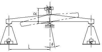
[0016] like figure 1 Shown is a schematic diagram of the measurement principle of the present invention, if weights W with different weights 1 and W 2 Placed on a weight pan, standard torque beams and flexures will deflect by an angle θ. The moment to deflect the flexure to this angle can be expressed as:

[0017] Since the deformation angle θ is very small, the above formula can be written as:

[0018]

[0019] In the formula: M is the torque load; θ is the deflection angle of the flexible support; K is the stiffness coefficient of the flexible support; L is half the length of the standard torque beam; and is the vertical displacement at the end of the standard torque beam caused by the torque load . Therefore, the displacement Δs is proportional to the torque, where K is the stiffness coefficient determined by the characteristics of the flexible support itself, which can be tested and calibrated in advance. Therefore, the torque load M can be tested...


PUM


Abstract

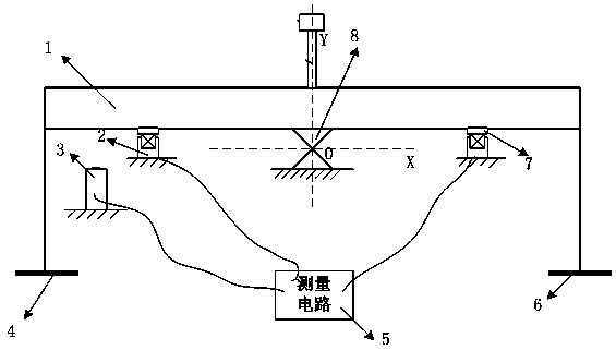
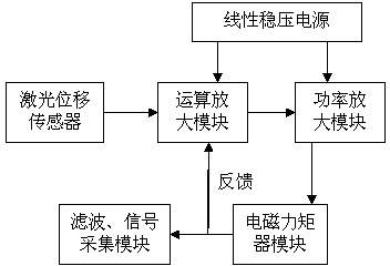
The invention relates to a flexible support based torque calibration and measurement device. Left and right scale pans used for hanging of weights are symmetrically mounted on two sides of a standard torque beam through elastic pieces. A rotation center 'O' of a flexible support coincides with a central axis 'Y' of the standard torque beam. A laser displacement sensor mounted on a base is arranged below the lower end face of the standard torque beam. Left and right electromagnetic torquers are symmetrically mounted on two sides of the lower end face of the standard torque beam. On the condition of a torque load, the laser displacement sensor transmits measured electric signals of displacement variation, of a laser sensor probe and a standard torque lower end face, caused by the torque load to the left electromagnetic torquer or the right electromagnetic torquer after the electric signals are processed by a measuring circuit so as to control the left electromagnetic torquer or the right electromagnetic torquer to generate electromagnetic force to level the standard torque beam. The flexible support based torque calibration and measurement device has the advantage that measurement precision is improved to the utmost by comprehensive measures such as an electromagnetic force equilibrium system, the high-precision laser displacement sensor and a rapid signal tracking and measuring system.

Description

technical field [0001] The invention relates to a torque calibration measurement device, in particular to a torque calibration measurement device based on flexible support. Background technique [0002] As a main parameter of mechanics, torque is widely used in aerospace, aviation, ships, weapons and other industries for its accurate measurement, calibration and control. The importance of torque measurement and calibration has been valued by developed countries. The advanced countries represented by Germany are vigorously developing advanced high-precision torque measurement standard devices to meet the growing needs of military and civilian industries. The torque standard device is a device used to reproduce the standard torque value and transmit the value. It is widely used in the verification and calibration of various torque meters and torque sensors. Most of the current torque standard devices are static weight, that is, the equipment is calibrated or calibrated by ad...

Claims


Application Information

Patent Timeline
IPC IPC(8): G01L3/00
Inventor 齐红丽李涛商维绿严康平王佩君满卫芳
Owner 中国船舶重工集团公司第七0四研究所
Learn More