Test device and method for positively emitting led light strips
A technology of LED light strips and LED lights, which is applied in the direction of lamp testing, optical performance testing, single semiconductor device testing, etc., and can solve problems such as slow detection speed, slow test speed, and poor resolution
- Summary
- Abstract
- Description
- Claims
- Application Information
AI Technical Summary
Problems solved by technology
Method used
Image
Examples
Embodiment 1
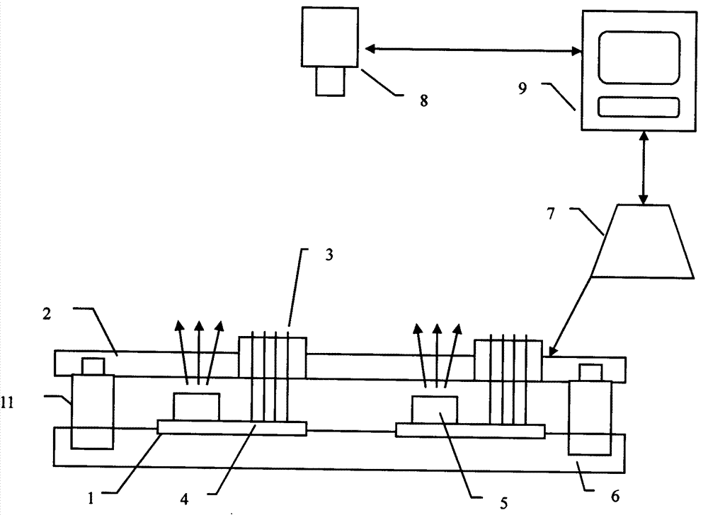
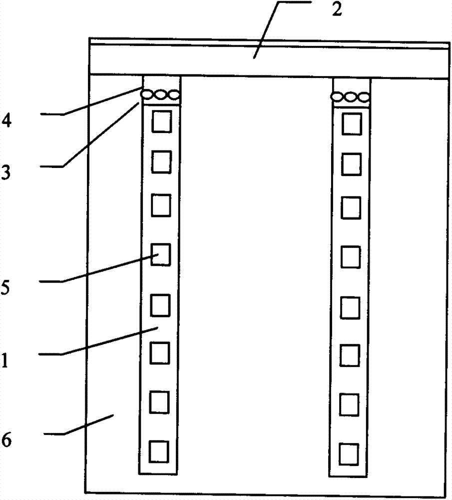
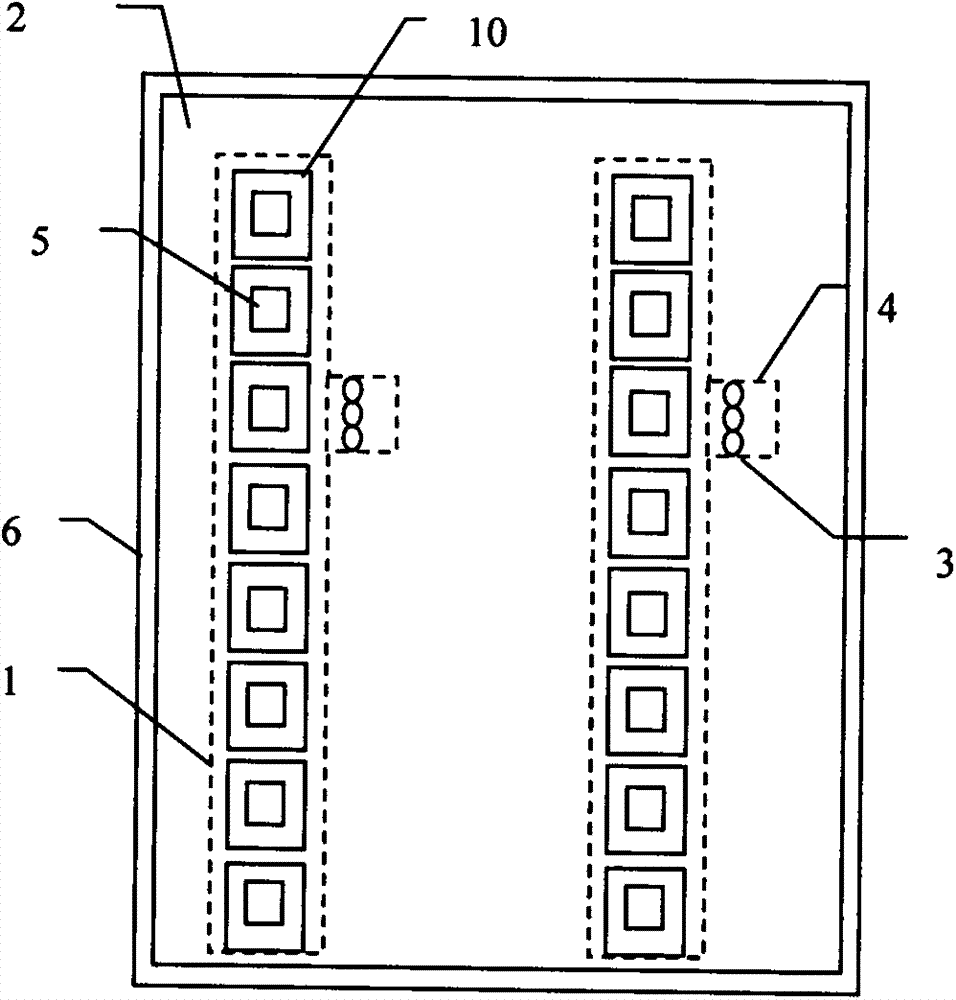
[0037] Embodiment one: if figure 1 As shown, the positive-emitting positive-emitting LED light bar test device includes a light bar 1, a light bar carrier 6, a light bar power module 7, a light bar test board 2, a digital camera 8, and a calculation control unit 9. The light bar 1 There are a plurality of LED lights 5 on it, and there are multiple light bars 1. The light bar 1 is fixed on the light bar carrier 6, and the light bar power module 7 indirectly supplies power to the light bar 1 through the light bar test board 2. The light bar board pin 4 of the light bar 1 is connected to the light bar test board 2, the power terminal of the light bar test board 2 is connected to the light bar power module 7, and the control terminal of the light bar power module 7 is connected to the computer control unit 9. Specific implementation methods, such as figure 1 As shown, a PIN pin 3 is fixed on the light bar test board 2 , one end of the PIN pin 3 is tied to the pin 4 of the light ...
Embodiment 2
[0043] Embodiment two: if Figure 5 As shown, the difference from Embodiment 1 is that the light strip test board 2 is an opaque plate, the light transmission device 10 is a first light transmission hole 13, and the first light transmission hole 13 is located on the light strip test board 2 , which is located directly above the LED light 5. In this way, the light of the positively emitting LED lamp 5 can normally pass through the light bar test board 2 and shine on the digital camera 8 for imaging. In addition, the difference from the above-mentioned embodiment is that the pins 4 of the light bar board on the LED light bar 1 are led to the edge of the light bar carrier 6 through the light bar carrier 6, and the light bar power supply module 7 is directly connected to the light bar The light strip board pin 4 on the edge of the strip carrier 6 is connected.
Embodiment 3
[0044] Embodiment three: as Figure 6 As shown, the difference from Embodiment 1 is that the light-transmitting device 10 is a light-guiding device, and the light-guiding device is a first light-guiding post 14, and the first light-guiding post 14 is fixed on the light bar test board 2, which Located directly above the LED lamp 5. Such as Figure 7 As shown, the upper surface of the first light guide post 14 is an atomized surface, and the atomized surface is the atomized surface 12 after grinding. Such as Figure 8 As shown, the atomized surface is a layer of atomized film 15 attached to the first light guide post 14 .
PUM
 Abstract
Description
Claims
Application Information
 - R&D
- Intellectual Property
- Life Sciences
- Materials
- Tech Scout
- Unparalleled Data Quality
- Higher Quality Content
- 60% Fewer Hallucinations
Browse by: Latest US Patents, China's latest patents, Technical Efficacy Thesaurus, Application Domain, Technology Topic, Popular Technical Reports.
© 2025 PatSnap. All rights reserved.Legal|Privacy policy|Modern Slavery Act Transparency Statement|Sitemap|About US| Contact US: help@patsnap.com


