
Quick solving method on basis of light intensity transfer equation of discrete cosine transform

A technology of discrete cosine transform and light intensity transmission equation, which is applied in the field of fast solution of light intensity transmission equation, can solve problems such as the influence of recovery phase accuracy, low algorithm solution efficiency, difficulty in meeting high-speed, real-time applications, etc., to achieve simple and efficient, Improved accuracy, low external storage effect

Inactive Publication Date: 2015-02-04
NANJING UNIV OF SCI & TECH
View PDF0 Cites 0 Cited by
  • Summary
  • Abstract
  • Description
  • Claims
  • Application Information

AI Technical Summary

Problems solved by technology

Usually, simple periodic boundary conditions or uniform Dirichlet boundary conditions and Neumann boundary conditions are used. When these simplified boundary conditions cannot be satisfied, the accuracy of the recovered phase will be greatly affected
On the other hand, the algorithm solution efficiency is low, and it is difficult to meet the occasions of high-speed and real-time applications.

Method used


Image

  • Quick solving method on basis of light intensity transfer equation of discrete cosine transform
  • Quick solving method on basis of light intensity transfer equation of discrete cosine transform
  • Quick solving method on basis of light intensity transfer equation of discrete cosine transform

Examples


Embodiment

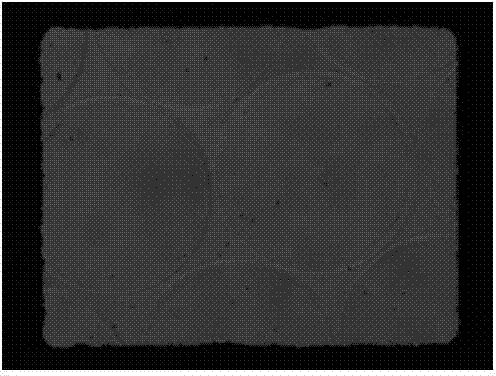
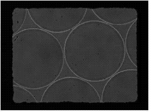
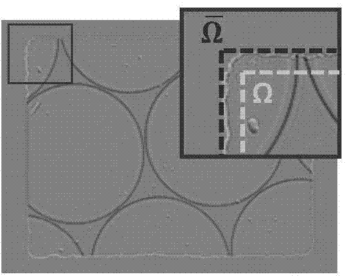
[0063] The experimental results of the present invention on the measurement of micro-optical elements are given below. The sample is a plano-convex quartz microlens array with a pitch of 250 μm (SUSS MicroOptics, lens diameter 240 μm, hexagonal package). In the experiment, the light intensity axial differential signal in the first step It is obtained by using the central finite difference method through two over-focus and under-focus light intensity distributions with a distance of ±550 μm. Figure 1(a) and Figure 1(b) show the collected focused I(r) and out-of-focus (Δz=-550μm) light intensity distribution I - (r). Figure 1(c) is the estimated light intensity axial differential signal The sub-image in the upper right corner is a partially enlarged display of the part in the red frame. Although the shape of the aperture is not an ideal rectangle (limited by the machining accuracy), the boundary signal around the aperture can be clearly observed, corresponding to the In ...


PUM


Abstract

The invention discloses a quick solving method on the basis of a light intensity transfer equation of discrete cosine transform. The method comprises the following steps of firstly, placing a diaphragm on the plane to be detected, acquiring three light intensity images, i.e. an under-focus light intensity image, a focusing light intensity image and an out-of-focus light intensity image, and performing numerical value difference on the under-focus light intensity image and the out-of-focus light intensity image to obtain an axial differential signal of light intensity; secondly, solving the inverse laplace of the axial differential signal of light intensity by using discrete cosine transform, on the basis of discrete cosine transform, solving the gradient of the inverse laplace of the axial differential signal of light intensity, dividing the gradient by the focusing light intensity image, and solving a divergence operation; finally, solving the inverse laplace on the result obtained in the step 3 by using discrete cosine transform, thus the solution, i.e. phase distribution to be solved, of the light intensity transfer equation is obtained. The precision of phase recovery is improved, the method is very simply and efficient, and the required external storage amount is also very low.

Description

technical field [0001] The invention belongs to phase recovery and quantitative phase imaging technology in optical measurement, in particular to a fast solution method of light intensity transmission equation based on discrete cosine transform. Background technique [0002] Phase recovery is an important topic in optical measurement and imaging technology, and phase imaging technology is playing an important role in both biomedical and industrial detection fields. Throughout the progress of optical measurement for nearly half a century, the most classic phase measurement method should be none other than interferometry. However, the disadvantages of interferometry are also very obvious: interferometry generally requires a highly coherent light source (such as a laser), which requires a more complex interferometric device; the introduction of an additional reference optical path leads to very harsh requirements for the measurement environment; The speckle coherent noise intr...

Claims


Application Information

Patent Timeline
Patent Type & Authority Applications(China)
IPC IPC(8): G06F19/00
Inventor 陈钱左超冯世杰孙佳嵩胡岩陶天阳顾国华张玉珍喻士领张良张佳琳
Owner NANJING UNIV OF SCI & TECH
Learn More