Shifting register unit, gate drive circuit and displayer

A shift register, drive control technology, applied in static memory, static indicator, digital memory information, etc., can solve the problem of harsh circuit life requirements, and achieve the effect of improving yield, suppressing threshold voltage drift, and prolonging life.

Active Publication Date: 2015-02-04
PEKING UNIV SHENZHEN GRADUATE SCHOOL
View PDF5 Cites 28 Cited by
  • Summary
  • Abstract
  • Description
  • Claims
  • Application Information

AI Technical Summary

Problems solved by technology

However, in large and medium-sized panel display applications, the driving circuit needs to be in the working mode for a longer time, which objectively puts forward more stringent requirements for the life of the circuit

Method used


Image

  • Shifting register unit, gate drive circuit and displayer
  • Shifting register unit, gate drive circuit and displayer
  • Shifting register unit, gate drive circuit and displayer

Examples


Embodiment 1

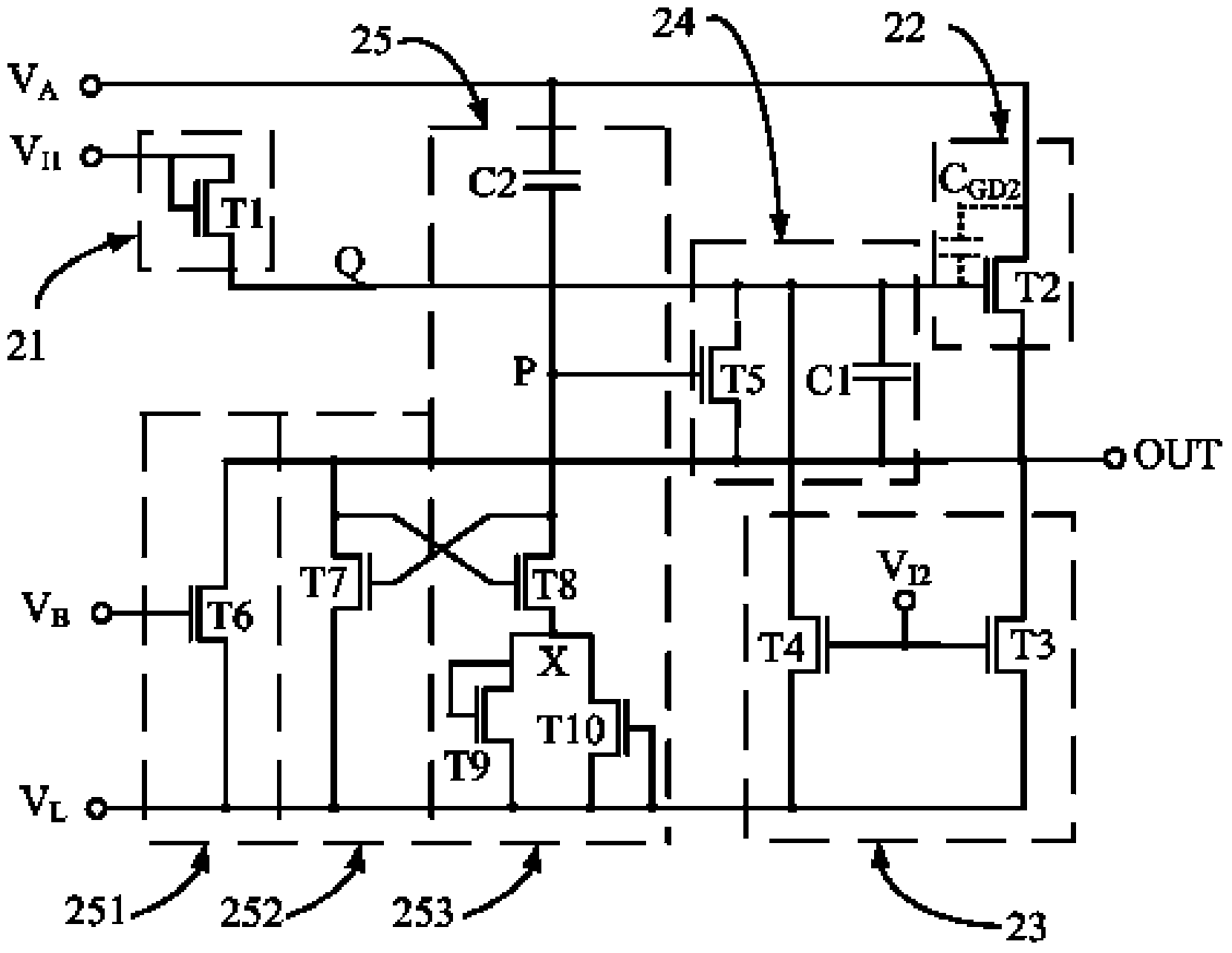
[0045] Please refer to figure 1 , the present application provides a shift register unit, including an input module 21 , a driving module 22 , a pull-down module 23 and a low-level maintaining module 25 .

[0046] The control terminal and the input terminal of the input module 21 are coupled to the first pulse signal terminal V I1 , for inputting the first pulse signal, the output terminal of which is coupled to the drive control terminal Q, and the input module 21 charges the drive control terminal Q in response to the high level of the first pulse signal.

[0047] The control terminal of the driving module 22 is coupled to the driving control terminal Q, and its input terminal is coupled to the first control signal terminal V A , for inputting the first control signal, whose output terminal is coupled to the signal output terminal V OUT , the drive module 22 outputs the high level of the first control signal to the signal output terminal V in response to the high level sig...

Embodiment 2

[0095] Please refer to Figure 4 , this embodiment provides another shift register unit. Compared with Embodiment 1, the difference is that the positive and negative bidirectional polarity potential generation unit 253 includes a second capacitor C2, an eighth transistor T8, and a reverse charging preventing transistor T9. and the reverse charging delay transistor T11, the gate of the eighth transistor T8 is coupled to the signal output terminal V OUT , its drain is coupled to the low-level maintenance control terminal P, its source is coupled to the intermediate node X, and the second capacitor C2 is connected to the first control signal terminal V A and the low-level maintenance control terminal P; the gate and drain of the reverse charging prevention transistor T9 are short-circuited, and coupled to the intermediate node X, and its source is coupled to the low potential terminal V L , the reverse charging prevention transistor T9 is used to turn off the low potential termi...

Embodiment 3

[0104] Please refer to Figure 5 , this embodiment provides another shift register unit. Compared with Embodiment 2, the difference is that: the positive and negative bidirectional polarity potential generating unit 253 includes a second capacitor C2, an eighth transistor T8, and a reverse charging preventing transistor T9 and a plurality of reverse charging delay transistors T11 connected in series, the gate of the eighth transistor T8 is coupled to the signal output terminal V OUT , its drain is coupled to the low-level maintenance control terminal P, its source is coupled to the intermediate node X, and the second capacitor C2 is connected to the first control signal terminal V A and the low-level maintenance control terminal P; the gate and drain of the reverse charging prevention transistor T9 are short-circuited, and coupled to the intermediate node X, and its source is coupled to the low potential terminal V L , the reverse charging prevention transistor T9 is used to ...


PUM


Abstract

The invention relates to a shifting register unit, a gate drive circuit and a displayer. The shifting register unit comprises an input module, a drive module, a pull-down module and a low level maintaining module; the low level maintaining module comprises a first maintaining unit, a second maintaining unit and a positive and negative bothway polarity potential generation unit; and the positive and negative bothway polarity potential generation unit is used for generating positive and negative bothway polarity potentials in the non-gating stage of the shifting register unit and outputting the positive and negative bothway polarity potentials to the low level maintaining control end. All transistors in the shifting register unit are prevented from staying under direct-current stress; the key transistors will stay under positive and negative bipolar pulse stress polarization within a period of time; threshold voltage shifting of the key transistors is accordingly restrained; and the service life of the circuit is prolonged. In addition, positive and negative bipolar voltage polarization is achieved through fewer transistors and fewer capacitors; the circuit design complex rate is low; and the rate of finished products is high. The displayer is high in reliability and low in production cost.

Description

technical field [0001] The present application relates to a display, in particular to a shift register unit and a gate driving circuit of the display. Background technique [0002] Active flat panel display has become the mainstream technology in the field of modern display. For the driving circuit of an active flat panel display, the traditional method is to connect the peripheral driving integrated circuit to the display panel by means of pressure sealing. In recent years, integrated display driving circuits have gradually become a research hotspot in flat panel display technology. The so-called integrated display driving circuit refers to making peripheral circuits such as gate driving circuit and data driving circuit on the display panel in the form of thin film transistors (TFTs) together with pixel TFTs. Compared with the traditional process, the method of integrated display driver can not only reduce the number of peripheral driver chips and their sealing procedures...

Claims


Application Information

Patent Timeline
Patent Type & Authority Applications(China)
IPC IPC(8): G09G3/20G09G3/36G11C19/28
Inventor 张盛东胡治晋廖聪维李文杰李君梅
Owner PEKING UNIV SHENZHEN GRADUATE SCHOOL
Why Eureka
Try Eureka