Injection reinforced bipolar transistor of insulated gate

A bipolar transistor, injection enhancement technology, applied in the direction of semiconductor devices, electrical components, circuits, etc.

Active Publication Date: 2015-02-04
中国东方电气集团有限公司
View PDF6 Cites 2 Cited by
  • Summary
  • Abstract
  • Description
  • Claims
  • Application Information

AI Technical Summary

Problems solved by technology

[0005] In the above patent, the gate of CN200920192176.6 is planar, and the innovation of CN201210333321.4 lies in the back, that is, a dielectric layer is introduced at the corresponding position of the terminal of the collector. However, the front structure (trench gate side) is still a traditional structure, so there is still the problem of low carrier concentration in the conduction process.

Method used


Image

  • Injection reinforced bipolar transistor of insulated gate
  • Injection reinforced bipolar transistor of insulated gate
  • Injection reinforced bipolar transistor of insulated gate

Examples


Embodiment 1

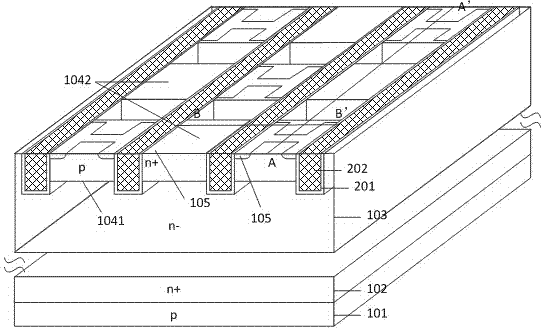
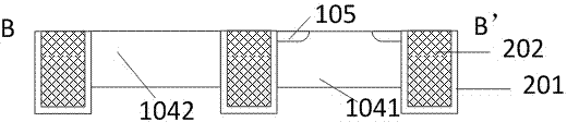
[0040] An injection-enhanced insulated gate bipolar transistor includes a p-type collector 101, a carrier diffusion layer 103 is arranged on the p-type collector 101, and a plurality of Trench 202, multiple rows of p-type mixed regions are arranged laterally on the carrier diffusion layer 103, each row of p-type mixed regions includes a plurality of independent p-type active regions 1041 and p-type inactive regions 1042, each block The intervals are separated by the grooves 202; the p-type active regions 1041 and p-type inactive regions 1042 on each row of p-type mixed regions are arranged at intervals, and the p-type active regions 1041 and p-type active regions 1041 and The p-type inactive regions 1042 are arranged at intervals, and each of the p-type active regions 1041 is provided with an n-type emitter 105 , and the n-type emitter 105 is H-type.

[0041] The bipolar transistor of the present application is provided with a stripe-like periodic separation cell structure, an...

Embodiment 2

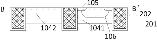
[0043] An injection-enhanced insulated gate bipolar transistor includes a p-type collector 101, a carrier diffusion layer 103 is arranged on the p-type collector 101, and a plurality of Trench 202, multiple rows of p-type mixed regions are arranged laterally on the carrier diffusion layer 103, each row of p-type mixed regions includes a plurality of independent p-type active regions 1041 and p-type inactive regions 1042, each block The intervals are separated by the grooves 202; the p-type active regions 1041 and p-type inactive regions 1042 on each row of p-type mixed regions are arranged at intervals, and the p-type active regions 1041 and p-type active regions 1041 and The p-type inactive regions 1042 are arranged at intervals, and each of the p-type active regions 1041 is provided with an n-type emitter 105 , and the n-type emitter 105 is H-type.

[0044] A field stop layer 102 is provided between the p-type collector electrode 101 and the carrier diffusion layer 103 . Th...

Embodiment 3

[0051] An injection-enhanced insulated gate bipolar transistor includes a p-type collector 101, a carrier diffusion layer 103 is arranged on the p-type collector 101, and a plurality of Trench 202, multiple rows of p-type mixed regions are arranged laterally on the carrier diffusion layer 103, each row of p-type mixed regions includes a plurality of independent p-type active regions 1041 and p-type inactive regions 1042, each block The intervals are separated by the grooves 202; the p-type active regions 1041 and p-type inactive regions 1042 on each row of p-type mixed regions are arranged at intervals, and the p-type active regions 1041 and p-type active regions 1041 and The p-type inactive regions 1042 are arranged at intervals, and each of the p-type active regions 1041 is provided with an n-type emitter 105 , and the n-type emitter 105 is H-type.

[0052] A field stop layer 102 is provided between the p-type collector electrode 101 and the carrier diffusion layer 103 . Th...


PUM


Abstract

The invention relates to the field of power semiconductor devices, in particular to an injection reinforced bipolar transistor of an insulated gate. The injection reinforced bipolar transistor comprises a p-type collector electrode, wherein a carrier diffusion layer is arranged on the p-type collector electrode. A plurality of grooves are longitudinally arranged on the carrier diffusion layer, and a plurality of rows of p-type mixing zones are transversely arranged on the carrier diffusion layer. Each row of p-type mixing zones comprises a plurality of independent p-type active zones and a plurality of independent p-type non-active zones, and the zones are separated by the grooves. The injection reinforced bipolar transistor is provided with strip-shaped periodic separate cell structures, emitting electrodes are correspondingly in separate shapes, accordingly holes generate the accumulative effect in the zones not covered by the emitting electrodes, further the carrier concentration of the zones close to the grooves is improved, and the on-state voltage drop is reduced.

Description

technical field [0001] The invention relates to the field of power semiconductor devices, and mainly relates to an injection-enhanced insulated gate bipolar transistor. Background technique [0002] Insulated gate bipolar transistors are widely used in the core control field of the power electronics industry. Trench gate is one of the core technologies of this type of product. Its main purpose can achieve greater current density and smaller conduction voltage drop, thereby Reduce device size and reduce power consumption. When the traditional insulated gate bipolar transistor is manufactured with a front structure (trench gate side), it usually adopts the method of full coverage of the cell area, which will cause the holes to quickly overflow the emitter when the device is in operation, reducing the area near the trench. The carrier concentration is low, so that the reduction of the conduction voltage drop is limited. [0003] The bipolar transistor structure has also been ...

Claims


Application Information

Patent Timeline
Patent Type & Authority Applications(China)
IPC IPC(8): H01L29/739H01L29/06H01L29/08H01L29/423
CPCH01L29/0603H01L29/0696H01L29/08H01L29/41708H01L29/7393
Inventor 胡强王思亮张世勇
Owner 中国东方电气集团有限公司
Why Eureka
Try Eureka