
Rectifying unit structure

A rectifier unit and rectifier bridge technology, which is applied in the direction of transforming equipment structural parts, electrical components, electrical equipment structural parts, etc., can solve problems such as poor heat dissipation, complicated electrical connections, poor contact rectifier components, etc., and achieve rectification circuit Simple and clear, safe and reliable insulation protection, and reasonable pipeline layout

Inactive Publication Date: 2015-02-04
BEIJING RONGXIN HUIKE TECH
View PDF3 Cites 6 Cited by
  • Summary
  • Abstract
  • Description
  • Claims
  • Application Information

AI Technical Summary

Problems solved by technology

The disadvantages of this structure are that the layout is simple, the overall space occupation is large, the electrical connection is complicated, the disassembly and maintenance are inconvenient, and some solid radiators are large in size and the heat dissipation capacity is not strong, resulting in increased loss and waste of space.
At the same time, the integral press-fit water-cooling rectifier unit structure used in the past is to press-fit the rectifier elements into an open whole through several screws, and the water-cooling pipelines are distributed outside, and the space utilization rate is not high.
Moreover, the outstanding problem is that the conductive contact surface of this structure is unevenly stressed, which can easily cause poor contact or compress and deform the rectifier element, directly affecting the electrical performance or even burning out the element.

Method used


Image

  • Rectifying unit structure
  • Rectifying unit structure
  • Rectifying unit structure

Examples


Embodiment Construction

[0018] The present invention will be described in detail below in conjunction with the accompanying drawings, but it should be pointed out that the implementation of the present invention is not limited to the following embodiments.

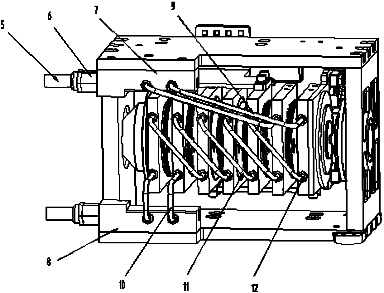
[0019] See figure 1 , The frame of the rectification unit includes a pressing side plate 1 , an upper plate 2 , a pressing side plate 3 and a lower plate 4 . The compression side plate 1, the compression side plate 3 and the upper plate 2 and the lower plate 4 are connected by high-strength bolts; the compression side plate 1 and the compression side plate 3 are provided with grooves, on the basis of ensuring the strength The structural weight is effectively reduced, and there are mounting holes and pin holes for the string pressing mechanism; the upper plate 2 is provided with the mounting holes for the water channel 7; the lower plate 4 is provided with the mounting holes for the water channel 8; There is a tool hole for easy internal installa...


PUM


Abstract

The invention discloses a rectifying unit structure. The rectifying unit structure comprises a frame, a rectifying bridge unit and a water cooling pipeline system, wherein the frame comprises upper and lower base plates and side plates on the two sides; the rectifying bridge unit is in a press string form, and comprises a top peg, a guide sleeve, a disc spring, a gasket, an insulating disc, a water-cooled radiator, a diode, a top column, a bus bar and a discharge resistor; the water cooling pipeline system comprises a quick joint, a water inlet and outlet passage, a pipeline, a pipe joint and a sealing member. The rectifying unit structure has the advantages that the power device, the radiating device, the bus bar and the like are arranged in the frame by the unit through a press string mechanism, the structure is more compact and attractive, the disassembly, assembly and maintenance are facilitated, the conductive contact is more uniform, and the electric performance is good; the radiating mode is water-cooled radiating, the radiating capacity is high, and the high-power radiating requirement can be met; the water cooling pipeline system is arranged on the outer side of the unit, is good in sealing, convenient to disassemble and assemble and an interface can be quickly plugged and pulled; the bus bar is skilful and rational in design, and the insulation protection is safe and reliable.

Description

technical field [0001] The invention relates to a rectification unit structure, in particular to a rectification unit structure used in the field of high-power frequency conversion. Background technique [0002] With the continuous development of power electronics technology, the performance of power components is constantly upgraded, and the size is also getting larger and larger. The spatial layout of the overall structure, the reliable contact of the conductive contact surface, and the heat dissipation capacity of the radiator are particularly important for the electrical performance. Generally, the structural layout of the rectification unit is generally to simply install and fix the rectification element and the heat dissipation device, and then form a rectification circuit through electrical connection. The disadvantages of this structure are that the layout is simple, the overall space is large, the electrical connection is complicated, disassembly and maintenance ar...

Claims


Application Information

Patent Timeline
IPC IPC(8): H02M7/00H05K7/20
CPCH02M7/003H05K7/20927
Inventor 顾晓聪王文龙高玉瑞张海涛赵亮张瑜
Owner BEIJING RONGXIN HUIKE TECH
Features
  • Generate Ideas
  • Intellectual Property
  • Life Sciences
  • Materials
  • Tech Scout
  • Unparalleled Data Quality
  • Higher Quality Content
  • 60% Fewer Hallucinations
Learn More