Method for avoiding pre-ignition in internal combustion engine and internal combustion engine and vehicle
A technology of pre-ignition, internal combustion engine, applied in the direction of internal combustion piston engine, combustion engine, engine ignition, etc.
- Summary
- Abstract
- Description
- Claims
- Application Information
AI Technical Summary
Problems solved by technology
Method used
Image
Examples
Embodiment Construction
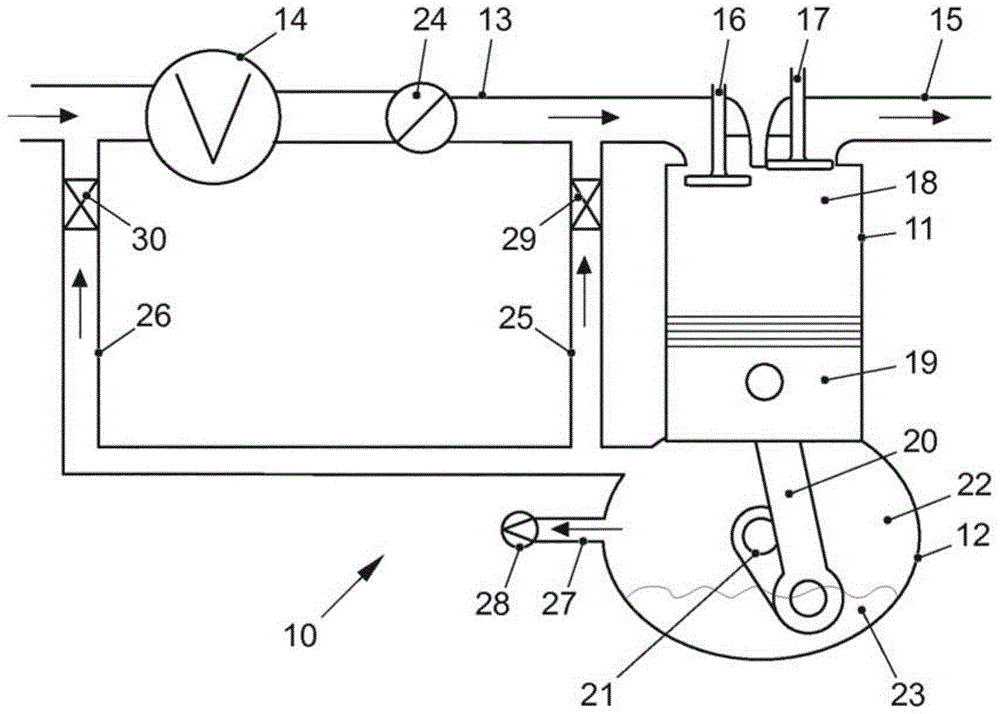
[0025] figure 2 Internal combustion engine 10 is shown with cylinders 11 , crankcase 12 , intake manifold 13 , compressor 14 and exhaust manifold 15 . An inlet valve 16 and an outlet valve 17 are arranged in the cylinder head of the cylinder 11 . Arranged in the combustion chamber 18 of the cylinder 11 is a piston 19 which drives a crankshaft 21 of the internal combustion engine 10 via a connecting rod 20 . The crankshaft 21 is located in the inner space 22 of the crankcase 12 . Furthermore, lubricating oil 23 is also present in interior space 22 , the lubricating oil for lubricating the movable parts of internal combustion engine 10 being pumped into the internal combustion engine by means of an oil pump not shown. Arranged in the intake manifold 13 is a throttle valve 24 for regulating the amount of fresh air supplied to the cylinders 11 in order to control the load of the internal combustion engine 10 . Internal combustion engine 10 also has other components, such as fu...
PUM
 Abstract
Description
Claims
Application Information
 - R&D
- Intellectual Property
- Life Sciences
- Materials
- Tech Scout
- Unparalleled Data Quality
- Higher Quality Content
- 60% Fewer Hallucinations
Browse by: Latest US Patents, China's latest patents, Technical Efficacy Thesaurus, Application Domain, Technology Topic, Popular Technical Reports.
© 2025 PatSnap. All rights reserved.Legal|Privacy policy|Modern Slavery Act Transparency Statement|Sitemap|About US| Contact US: help@patsnap.com


