

Automatic spot welding machine
A spot welding machine, automatic technology, applied in welding equipment, welding equipment, resistance welding equipment and other directions, can solve the problems of unguaranteed missed inspection, low production efficiency, wrong inspection, etc., to improve the operation speed, save labor costs, The effect of speeding up the production schedule
- Summary
- Abstract
- Description
- Claims
- Application Information
AI Technical Summary
Problems solved by technology
Method used
Image

Examples
Embodiment Construction
[0016] In order to make the technical means, creative features, goals and effects achieved by the present invention easy to understand, the present invention will be further described below in conjunction with specific embodiments.
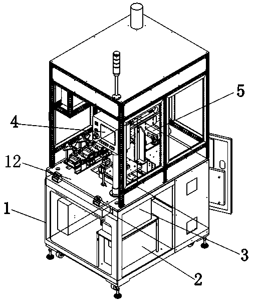
[0017] refer to figure 1 , the specific embodiment adopts the following technical solutions: an automatic spot welding machine, including a frame 1 and a welding power source 2 arranged on the frame 1, the welding power source is connected with a welding transformer 3, a pressure monitor 4 and A rotary welding mechanism 5 to prevent electrode adhesion, the rotary welding mechanism 5 includes (X, Y, Z) three-axis servo module feed system, the welding power supply 2, welding transformer 3 and pressure monitor 4 are connected with each other The above-mentioned rotary welding mechanism 5 is connected.
[0018] During specific implementation, the rotary welding mechanism 5 for preventing electrode adhesion can be moved to the automobile ignition coil...
PUM
 Abstract
Description
Claims
Application Information