Heat exchanger for cooling a vehicle battery, in particular for hybrid or electric vehicles

A technology of hybrid electric vehicles and heat exchangers, applied in heat exchange equipment, secondary batteries, indirect heat exchangers, etc., can solve the problems of low energy efficiency of motor vehicles, and achieve the effect of reducing installation costs

Inactive Publication Date: 2015-02-11
BEHR GMBH & CO KG
View PDF11 Cites 7 Cited by
  • Summary
  • Abstract
  • Description
  • Claims
  • Application Information

AI Technical Summary

Problems solved by technology

The energy efficiency of motor vehicles equipped with such cooling bodies is rather low

Method used


Image

  • Heat exchanger for cooling a vehicle battery, in particular for hybrid or electric vehicles
  • Heat exchanger for cooling a vehicle battery, in particular for hybrid or electric vehicles
  • Heat exchanger for cooling a vehicle battery, in particular for hybrid or electric vehicles

Examples


Embodiment Construction

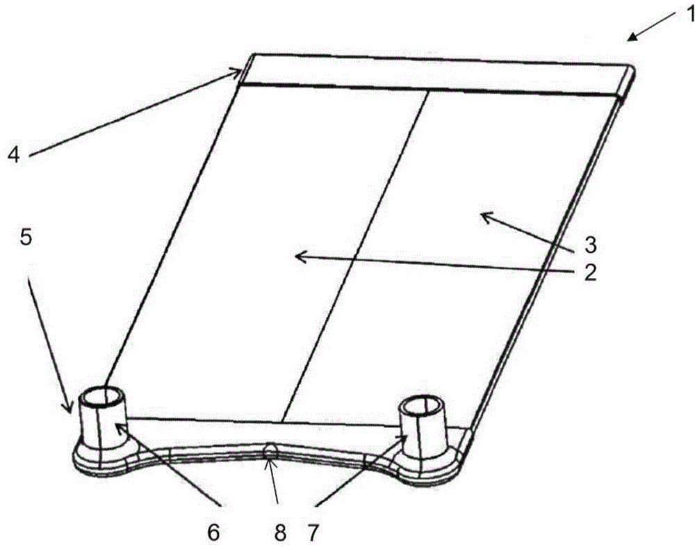
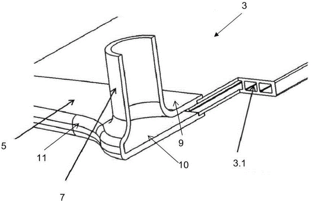
[0025] figure 1 A first exemplary embodiment of a heat exchanger according to the invention is shown. The heat exchanger 1 here comprises two multi-lumen tubes 2 , 3 which are arranged between two fluid collectors 4 , 5 . The two multilumen tubes 2 , 3 and the two fluid collectors 4 , 5 are here made entirely of plastic. figure 1 The heat exchanger 1 shown is designed as a U-shaped flow cooler. This heat exchanger 1 is characterized in that the inlet branch 6 for the fluid of the cooling medium and the outlet branch 7 for this fluid are arranged on the same fluid collector 5 . The inlet branch 6 is arranged here in the region of the first multi-lumen tube 2 , while the outlet branch 7 lies opposite the second multi-lumen tube 3 .

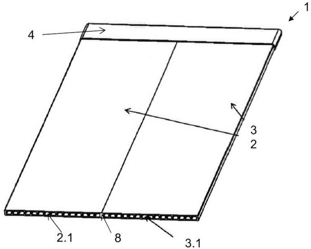
[0026] figure 2 Parts of the multi-lumen tubes 2 and 3 are shown, from which it can be seen that each multi-lumen tube 2, 3 has a plurality of fluid channels 2.1 or 3.1. In the described U-shaped flow cooler, the fluid flows via the fluid coll...


PUM


Abstract

A heat exchanger for cooling a vehicle battery, in particular for hybrid or electric vehicles, having at least one fluid collector made of plastic, which is connected to at least one cooling element. In a heat exchanger in which the energy efficiency of the motor vehicle is increased, the cooling element is designed as a plastic tube, in which a fluid is conducted from the first fluid collector to a second fluid collector.

Description

technical field [0001] The invention relates to a heat exchanger for cooling a vehicle battery, in particular a vehicle battery of a hybrid or electric vehicle. Background technique [0002] High-performance batteries, such as lithium-ion batteries, are used in various forms as energy storage in hybrid or electric vehicles. During operation of such a high-power battery cell, heat loss occurs which heats the high-power battery cell. Lithium-ion batteries, however, age significantly faster starting from the structurally-dependent temperature, so that the service life of the lithium-ion battery is undesirably shortened. To overcome this consequence, a cooling body is placed on the Li-ion battery. [0003] The low ambient temperature of a Li-ion battery can also have a huge impact on the functionality of the battery. It is therefore necessary to keep the temperature of the energy store within a predetermined range. [0004] An energy storage unit is known from WO 2010 / 037797...

Claims


Application Information

Patent Timeline
Patent Type & Authority Applications(China)
IPC IPC(8): F28F21/06H01M10/613
CPCH01M10/5004F28D1/03F28D1/05358F28F3/12F28F9/02F28F21/065H01M10/613H01M10/625H01M10/647H01M10/6557Y02E60/10
Inventor 约尔根·奥托马尔塔·卢卡-加博尔凯蒂亚·亨德里克斯海科·内夫卡罗琳·简森
Owner BEHR GMBH & CO KG
Why Eureka
Try Eureka