Aging and early failure detection method and detection apparatus of solid relay

A solid-state relay and early failure technology, which is applied in the direction of circuit breaker testing, etc., can solve the problems of wasting manpower, discrete components can not be directly observed, qualified, etc., to achieve improved sampling accuracy, fast measurement speed, and simple operation Effect

Active Publication Date: 2015-02-11
西安宝力电子科技有限公司
View PDF6 Cites 2 Cited by
  • Summary
  • Abstract
  • Description
  • Claims
  • Application Information

AI Technical Summary

Problems solved by technology

[0007] Since the input (control) circuit, isolation (coupling) and output (load) circuit of the solid state relay or solid time delay relay are generally sealed in a metal case, it is impossible to directly observe whether the internal discrete components are soldered or not.
At present, two methods are mainly adopted: one is to add power to the input end of the solid-state relay or solid-state time-delay relay, add load power to the output of the solid-state relay or solid-state time-delay relay, and measure the voltage drop on the contact with a voltmeter. If the measured voltage drop is within the specified range, it is judged that the solid state relay or solid state time delay relay is qualified. This method is not only troublesome, time-consuming, and manpower wasted, but also cannot ensure that the parameters of the aged solid state relay or solid state time delay relay are still qualified. ; The second is to measure the parameters with a special solid state relay or solid time delay relay test instrument, and then age it. Although the test speed is improved compared with the first method, it cannot guarantee that the aged solid state relay or solid time delay relay will be tested after aging. when the relay is still qualified

Method used


Image

  • Aging and early failure detection method and detection apparatus of solid relay

Examples


Embodiment

[0022] In an embodiment, a detection method for aging and early failure of a solid state relay includes the following steps:

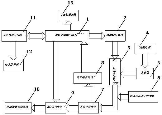
[0023] 1) Connect the field programmable gate array to the excitation output circuit, connect the positive output of the excitation output circuit to the positive input terminal of the solid state relay or solid delay relay, and connect the negative output of the excitation output circuit to the negative input of the solid state relay or solid state delay relay The positive output terminal of the load power supply is connected in series with the load box and then the positive output terminal of the solid state relay or solid delay relay. The negative output terminal of the load power supply is connected to the negative output terminal of the solid state relay or solid state delay relay. The contact status indicator circuit is positive. The terminal is connected to the positive output terminal of the solid state relay or the solid state delay relay, the neg...


PUM


Abstract

Disclosed is an aging and early failure detection method of a solid relay. The method comprises the following steps: 1), applying an excitation signal to the solid relay, and an A/D sampling circuit acquiring a voltage drop of a moving connection contact or a voltage drop of a moving disconnection contact, a voltage drop of a moving connection-disconnection fault or a voltage drop of a moving connection-binding fault; 2), an FPGA starting a timer at the rising edge of the excitation signal, when load currents flow through the solid relay, outputting a trigger signal, and when the trigger signal is detected, stopping the timer; 3), the FPGA starting the timer at the falling edge of a pulse signal, a level trigger circuit outputting the trigger signal, and when the FPGA detects the trigger signal, stopping the timer; and 4), storing acquired data in an external storage circuit, and a display displaying a result. The detection apparatus comprises the FPGA, an excitation output circuit, a load power source, a load case, a contact state indicating lamp circuit, a sampling voltage dividing circuit, the level trigger circuit, the A/D sampling circuit, an external data storage circuit, an industrial control computer and a fault alarm. The detection is simple, and the aging detection is rapid, accurate and automatic.

Description

Technical field [0001] The invention belongs to the technical field of detection of solid state relays and solid state time delay relays, and specifically relates to a detection method and detection device for aging and early failure of solid state relays. Background technique [0002] Solid State Relays (SSR) is a kind of non-contact electronic switch, which is composed of discrete components, film fixed resistance network and chip, assembled by mixed technology to realize control loop (input circuit) and load loop The electrical isolation and signal coupling of the output circuit are realized by solid-state devices. There are no movable parts inside, which can achieve the purpose of connecting and disconnecting the circuit without contact and spark. Used in communication, remote control, telemetry, mechatronics and its power electronic equipment, solid state relay or solid state delay relay is composed of input (control) circuit, isolation (coupling) and output (load) circuit. ...

Claims


Application Information

Patent Timeline
Patent Type & Authority Applications(China)
IPC IPC(8): G01R31/327
Inventor 武军会景占荣李军银高田将龙驹羊彦杨春雷巍伟
Owner 西安宝力电子科技有限公司
Why Eureka
Try Eureka