Realization method of relay driving module applied to elevator control system

An implementation method and technology of driving modules, which are applied in the direction of relays, circuits, electrical components, etc., can solve the problems of effective level, relay K1 malfunction, etc.

Inactive Publication Date: 2015-02-11
JIANGSU XIDE ELEVATOR
View PDF4 Cites 3 Cited by
  • Summary
  • Abstract
  • Description
  • Claims
  • Application Information

AI Technical Summary

Problems solved by technology

When the control MCU is under certain circumstances, such as the program runs away or is always in the reset state, there may be an active level at the Ctr terminal, causing the relay K1 to malfunction

Method used


Image

  • Realization method of relay driving module applied to elevator control system
  • Realization method of relay driving module applied to elevator control system

Examples


Embodiment Construction

[0011] 1. Control signal

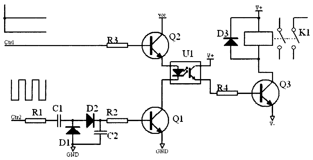
[0012] Such as figure 2 As shown, the effective signal of the control terminal Ctr1 is a level signal (the circuit is active at high level), and the effective signal of the control terminal Ctr1 is a signal with adjustable pulse width. When both the control terminal Ctr1 and the control terminal Ctr2 are valid signals, the relay coil is connected to both ends of the power supply to generate a driving current, and the relay operates.

[0013] 2. Conversion circuit

[0014] Such as figure 2 As shown, the level signal of the control terminal Ctr1 is connected to the base of the triode Q2 through the current limiting resistor R3, and the conduction between the input terminal of the optocoupler U1 and the power supply vcc is controlled by a meter; the pulse width adjustable square wave signal of the control terminal Ctr2 is limited The current resistor R1 and the DC blocking capacitor C1 are filtered by the capacitor C2 and then converted into a leve...


PUM


Abstract

The invention discloses a realization method of a relay driving module applied to an elevator control system. The realization method is mainly explained in two aspects including control signals and conversion circuits. A measure of avoiding relay false operation under the condition that program fleet occurs or the control system is always in the reset state by a certain reason is provided for the control system, so that the safety and the reliability of the elevator control are enhanced.

Description

technical field [0001] The invention relates to a method for realizing a relay drive module of an elevator control system. Background technique [0002] According to the survey, the number of elevators in China has exceeded 2 million. Elevators have entered the lives of ordinary people and are closely related to the lives of residents and have a large number. Elevator reliability determines the probability of failure or even accidents, and determines the stability of the elevator. [0003] In the elevator control system, the control signal output is basically carried out through the relay. For example, the output mode of the forward and reverse signal of the inverter on the main control computer board is the relay output. Relay control reliability determines the reliability of signal transmission. The working principle in the conventional design is shown in the attached figure _1. The relay K1 is driven by the control terminal Ctr meter and the current is limited by R1, an...

Claims


Application Information

Patent Timeline
Patent Type & Authority Applications(China)
IPC IPC(8): H01H47/02B66B1/06
CPCH01H47/005B66B1/06
Inventor 陈新会
Owner JIANGSU XIDE ELEVATOR
Why Eureka
Try Eureka