
Manufacturing method of semiconductor device

A manufacturing method and semiconductor technology, applied in the fields of semiconductor/solid-state device manufacturing, semiconductor devices, electric solid-state devices, etc., can solve the problems of load effect, etching stop, loss of inter-layer dielectric layer, etc., and achieve good structure, The effect of simplifying the etching process

Active Publication Date: 2015-02-11
SEMICON MFG INT (SHANGHAI) CORP
View PDF6 Cites 4 Cited by
  • Summary
  • Abstract
  • Description
  • Claims
  • Application Information

AI Technical Summary

Problems solved by technology

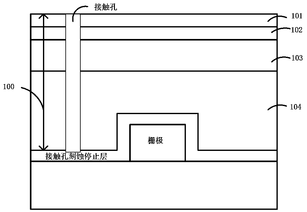
However, the formation of the M1-etch stop layer will have a loading effect
[0007] Because in the process of forming the contact hole in the prior art, only the etching of the dielectric anti-reflection coating can produce the effect of reducing the critical dimension of the contact hole. If the critical dimension of the contact hole is reduced in the step of etching the interlayer dielectric layer, the Problems causing etch stop
Moreover, when the calibration method of LRM (Line-Reflect-Match) is used to etch to form contact holes, more loss of the interlayer dielectric layer will be generated.

Method used


Image

  • Manufacturing method of semiconductor device
  • Manufacturing method of semiconductor device
  • Manufacturing method of semiconductor device

Examples


Embodiment Construction

[0027] In the following description, numerous specific details are given in order to provide a more thorough understanding of the present invention. It will be apparent, however, to one skilled in the art that the present invention may be practiced without one or more of these details. In other examples, some technical features known in the art are not described in order to avoid confusion with the present invention.

[0028] In order to thoroughly understand the present invention, detailed steps will be presented in the following description in order to explain the method for forming a contact hole proposed by the present invention. Obviously, the practice of the invention is not limited to specific details familiar to those skilled in the semiconductor arts. Preferred embodiments of the present invention are described in detail below, however, the present invention may have other embodiments besides these detailed descriptions.

[0029] It should be understood that when th...


PUM


Abstract

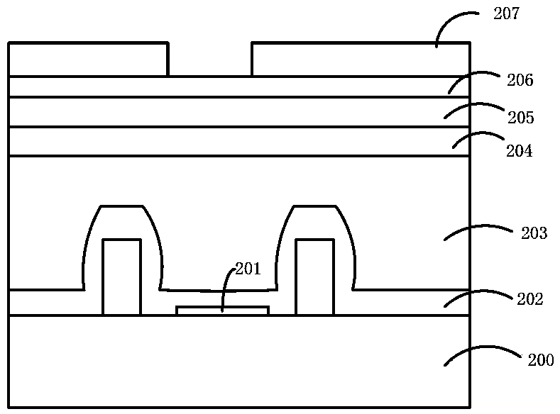
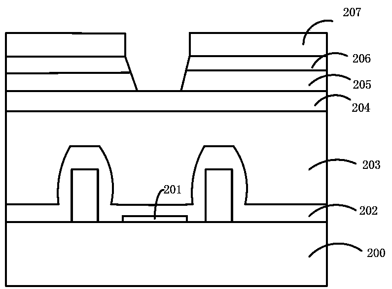
The invention provides a manufacturing method of a semiconductor device. The manufacturing method comprises the following steps: providing a semiconductor substrate, wherein a gate electrode and a side wall structure are formed on the semiconductor substrate, and a self-aligned metal silicide is formed on a source / drain region on the two sides of the gate electrode and the side wall structure; forming a first interlayer dielectric layer, a covering layer and a patterned photoresist layer on the semiconductor substrate in sequence; etching the covering layer and the first interlayer dielectric layer in sequence according to the patterned photoresist layer to expose a contact hole of the self-aligned metal silicide; filling metal in the contact hole; removing excess metal by using a chemical mechanical polishing process, wherein the loss of the first interlayer dielectric layer is not caused in the process of forming the contact hole through etching and in the metal chemical mechanical polishing process. According to the manufacturing process, the etching process can be simplified, the contact hole of a good structure is formed, and the formed contact hole meets the requirements of an integrated circuit.

Description

technical field [0001] The invention relates to a semiconductor manufacturing process, in particular to a method for forming a contact hole. Background technique [0002] As the manufacture of integrated circuits develops toward ultra-large-scale integrated circuits (ULSI), the internal circuit density is increasing, and the number of components contained is increasing and decreasing, making the surface of the wafer unable to provide enough area to make the required interconnection lines. . Therefore, in order to meet the increased demand for interconnection lines after component shrinkage, the design of multilayer metal interconnection lines with more than two layers has become a necessary method for VLSI technology. At present, the conduction between different metal layers is achieved by digging an opening in the insulating layer between the two metal layers and filling it with a conductive material to form a contact hole structure that conducts the two metal layers. The...

Claims


Application Information

Patent Timeline
Patent Type & Authority Applications(China)
IPC IPC(8): H01L21/768
CPCH01L21/76814H01L21/7684H01L2221/101H01L2221/1068
Inventor 王新鹏
Owner SEMICON MFG INT (SHANGHAI) CORP
Learn More