Machine-made-sand grain shape optimizing machine

A kind of sand and mechanism technology, applied in grain processing and other directions, can solve the problems that the fluidity, bulk density, gradation and other performance indicators of machine-made sand are difficult to meet, and affect the performance of concrete, so as to improve the fluidity and increase the compressive strength.

Active Publication Date: 2015-02-18
HENAN LIMING HEAVY IND SCI & TECH
View PDF7 Cites 1 Cited by
  • Summary
  • Abstract
  • Description
  • Claims
  • Application Information

AI Technical Summary

Problems solved by technology

The crushing of machine-made sand is usually completed by a sand making machine. Although the overall grain shape of the material produced by the sand making machine is mainly cubic, and the grain shape is good, due to the limitation of its crushing mechanism, the fluidity, bulk density, Performance indicators such as gradation are difficult to meet the requirements of high-quality concrete aggregates, which ultimately affects the improvement of concrete performance

Method used


Image

  • Machine-made-sand grain shape optimizing machine
  • Machine-made-sand grain shape optimizing machine
  • Machine-made-sand grain shape optimizing machine

Examples


Embodiment Construction

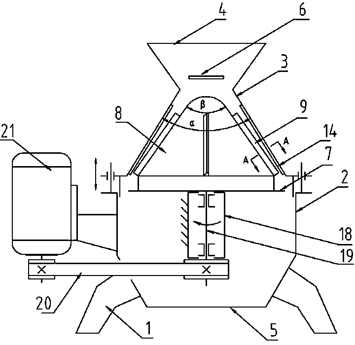
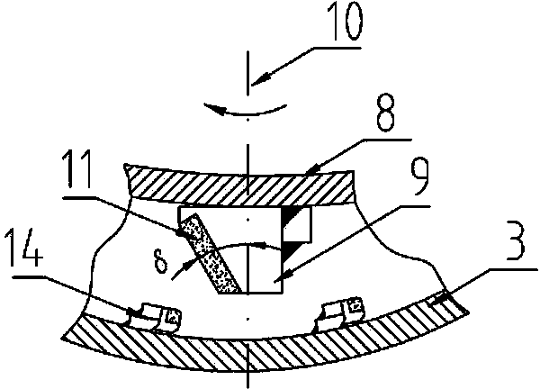
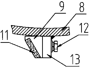
[0015] Such as figure 1 As shown, the machine-made sand particle shape optimization machine of the present invention includes a casing arranged on the machine base 1, the inner cavity of the casing is composed of a cylindrical lower chamber 2 and a conical upper chamber 3, and the feeding The mouth 4 is arranged on the top of the conical upper chamber 3, the discharge port 5 is arranged on the bottom of the cylindrical lower chamber 2, and a bulk material tray 6 is arranged below the feed inlet 4; the conical upper chamber The cone angle α of 3 is 70°, and the connection between the conical upper chamber 3 and the cylindrical lower chamber 2 is provided with a throwing tray 7, and a movable cone 8 is concentrically fixed on the upper surface of the throwing tray 7. The taper angle β of moving cone 8 is 65 °, and the maximum diameter of moving cone 8 is less than the diameter of throwing off material tray 7, and the diameter of throwing off material tray 7 is less than the diam...


PUM


Abstract

The invention discloses a machine-made-sand grain shape optimizing machine. The machine comprises a machine casing arranged on a machine base, wherein an inner cavity of the machine casing consists of a cylindrical lower cavity and a conical upper cavity, a material throwing disc is arranged at the communicating part of the conical upper cavity and the cylindrical lower cavity, a movable cone is concentrically fixed on the upper disc surface of the material throwing disc, the maximum diameter of the movable cone is smaller than the diameter of the material throwing disc, and the diameter of the material throwing disc is less than that of the cylindrical lower cavity; one or more scraping plates are fixed on the outer surface of the movable cone in the conical direction, the surfaces, facing the rotating direction, of the scraping plates are oblique surfaces, a wear-resistant lining plate is fixed on the inner surface of the conical upper cavity, a feed inlet is formed in the top of the conical upper cavity, and a material dispersing disc is arranged below the feed inlet; a main shaft which is driven by a power source to rotate is vertically arranged in the cylindrical lower cavity, and the upper part of the main shaft and the movable cone are concentrically and fixedly connected. The machine has the advantages that machine-made sand grains are processed by adopting grinding and low-energy crushing theories, and the effects of improving the mobility, the stacking density, the grading and the like of the machine-made sand grains are achieved.

Description

technical field [0001] The invention relates to production equipment for machine-made sand, in particular to a machine for optimizing the shape of machine-made sand grains. Background technique [0002] With the improvement of people's awareness of environmental protection and in order to reduce the damage to natural resources, the use of natural sand has been strictly restricted, and it will gradually withdraw from the building materials market and be replaced by machine-made sand. Machine-made sand belongs to the fine aggregate in concrete, which refers to rock particles crushed by machinery with a particle size of less than 4.75mm. The crushing of machine-made sand is usually completed by a sand making machine. Although the overall grain shape of the material produced by the sand making machine is mainly cubic, the grain shape is better, but due to the limitation of its crushing mechanism, the fluidity, bulk density, Performance indicators such as gradation are difficult...

Claims


Application Information

Patent Timeline
IPC IPC(8): B02C19/00
CPCB02C2/005B02C2/007B02C2/10
Inventor 杨松科赵大力
Owner HENAN LIMING HEAVY IND SCI & TECH
Why Eureka
Try Eureka