Wire drawing machine

A wire drawing machine and frame technology, applied in the field of plastic processing machinery, can solve problems affecting production progress, drawing ratio errors, and high labor intensity, and achieve reduced labor intensity, reduced production costs and use costs, and high transmission efficiency Effect

Active Publication Date: 2015-02-18
雁峰集团有限公司
View PDF10 Cites 8 Cited by
  • Summary
  • Abstract
  • Description
  • Claims
  • Application Information

AI Technical Summary

Problems solved by technology

But there are many problems in this way. The first is to replace the wire drawing machine of the sprocket. The sprocket must be replaced every time the drawing ratio is changed, which is extremely inconvenient and labor-intensive, which affects the production progress. Secondly, the speed is adjusted separately by double frequency conversion. wire drawing machine, the cost is high and sometimes there is a slight error in the drawing ratio when the voltage rises in the second half of the night, so it cannot meet the requirements of various raw materials and different quality requirements such as recycled materials, filler masterbatch mixtures, powder materials, and pellets. different requirements than

Method used


Image

  • Wire drawing machine
  • Wire drawing machine
  • Wire drawing machine

Examples


Embodiment 1

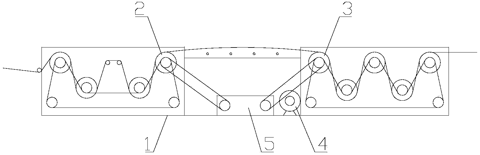
[0028] Such as figure 1 As shown, the present embodiment provides a wire drawing machine, including a frame 1, a traction roller 2, a stretching roller 3, a drive motor 4 and a gearbox 5, and the traction roller 2 and the stretching roller 3 are all positioned on the machine. On frame 1, after the extruder extrudes the plastic filament, it is pulled forward by the pulling roller 2 after being cooled, and stretched by the drawing roller 3 after heating. 3. When the rotating speed is slow, the plastic filament can be elongated and thinned to increase the strength.

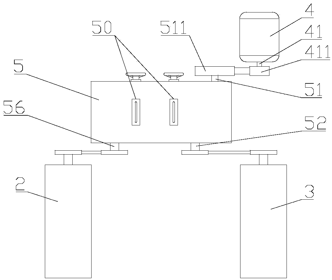
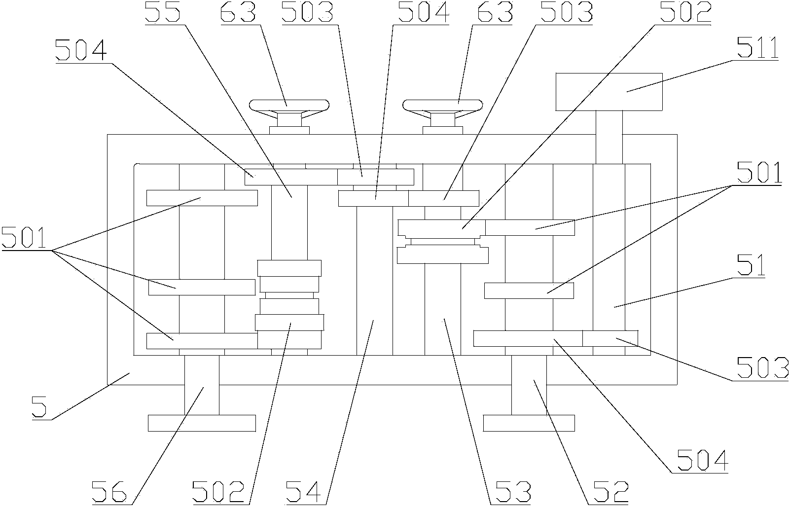
[0029] Combine below figure 2 and image 3 To illustrate the specific structure of the gearbox 5.

[0030] In the gearbox 5, an input shaft 51, a first output shaft 52, a first transition shaft 53, a second transition shaft 54, a third transition shaft 55 and a second output shaft 56 are sequentially arranged in parallel, and the driving motor 4 and the input shaft 51 drive The connection, preferably gear meshin...

Embodiment 2

[0038] See Figure 6 , The difference between this embodiment and Embodiment 1 is mainly in two points: First, the input shaft 51 and the first output shaft 52 are coaxial structures. In this embodiment, "coaxial structure" means that the input shaft 51 and the first output shaft 52 are completely composed of one shaft, one end of which is connected to the drive motor, and the other end is connected to the stretching roller. barrel drive connection. In this way, the transmission structure between the input shaft 51 and the first output shaft 52 can be omitted, and the first output shaft 52 can obtain a preset rotating speed through the input shaft 51 and the drive motor to reduce speed; secondly, on the second transition shaft Only one transition gear 505 is provided, the first transition shaft 53 is provided with a driving gear 503 meshing with the transition gear 505 on the second transition shaft 54, and the third transition shaft 55 is provided with a transition gear 503 ...

Embodiment 3

[0041] See Figure 7 , the difference between this embodiment and the first embodiment is that the slip gear 502 originally arranged on the third transition shaft 55 in the first embodiment is set on the second output shaft 56, while the first The three transmission gears 501 on the second output shaft 56 are arranged on the third transition shaft 55, and the principle of shifting is the same as that of the first embodiment, so it will not be repeated here.

[0042] The relationship between the input shaft 51 and the first output shaft 52 in this embodiment can also adopt the "coaxial structure" mentioned in the second embodiment.

[0043] Similar to this embodiment, the slip gear 502 on the first transition shaft 53 and the two transmission gears 501 on the first output shaft 52 can also be exchanged, that is, the two transmission gears 501 are located in the first transition On the shaft 53 , a slip gear 502 is provided on the first output shaft 52 . Therefore in addition ...


PUM


Abstract

The invention discloses a wire drawing machine, belongs to plastic processing machinery, and solves the problem that different requirements on extension ratio of different raw materials and different masses cannot be met in the prior art. In order to solve the problem, the invention adopts the technical scheme that an input shaft, a first output shaft, a transitional shaft set and a second output shaft are arranged in a gearbox in parallel in sequence; a drive motor is in transmission connection with the input shaft; the input shaft and the first output shaft are in transmission connection or form a coaxial structure; the first output shaft is in transmission connection with a draw roller; the second output shaft is in transmission connection with a pull roller; the first output shaft is in transmission connection with a transitional shaft set through a shifting gear set; the transitional shaft set is in transmission connection with the second output shaft through the shifting gear set; the shifting gear set comprises a sliding gear and at least two transmission gears; an adjusting component used for adjusting meshing of the sliding gear and different transmission gears is arranged in the gearbox body. The wire drawing machine is mainly applied to plastic wire drawing.

Description

technical field [0001] The invention relates to a plastic processing machine, in particular to a wire drawing machine. Background technique [0002] In some plastic products widely used in China, plastic wire drawing machines are used to process plastic raw materials into flat or round wires for weaving into plastic products, and according to different raw materials and different quality requirements, the drawing ratio of the wire drawing machine must be changed. At present, the wire drawing machines manufactured and used at home and abroad generally adopt the replacement of sprockets or double frequency conversion to adjust the speed respectively for changing the drawing ratio. But there are many problems in this way. The first is to replace the wire drawing machine of the sprocket. The sprocket must be replaced every time the drawing ratio is changed, which is extremely inconvenient and labor-intensive, which affects the production progress. Secondly, the speed is adjusted...

Claims


Application Information

Patent Timeline
Patent Type & Authority Applications(China)
IPC IPC(8): D01D5/16D01D13/02
CPCD01D5/16D01D13/00
Inventor 陈志淡邹虎生阳红祥陈向荣陈庆楷
Owner 雁峰集团有限公司
Why Eureka
Try Eureka