
Construction method of deep elevator shaft or water collection well

A construction method and the technology of collecting wells, which are applied in water conservancy projects, excavation, artificial islands, etc., can solve problems such as the inability to effectively curb the collection and infiltration of soil phreatic water, affect the quality of waterproof concrete molding, and cannot completely solve deep well templates, etc., to achieve reduction The difficulty of installation and dismantling, the improvement of construction quality, and the effect of simple installation

Active Publication Date: 2016-02-03
WUHAN YIYE CONSTR ENG
View PDF5 Cites 5 Cited by
  • Summary
  • Abstract
  • Description
  • Claims
  • Application Information

AI Technical Summary

Problems solved by technology

[0002] In the construction of elevator shafts or water collection wells when the groundwater level is high, the conventional membrane waterproofing process cannot effectively curb the accumulation and infiltration of soil water around the brick tire membrane even with continuous precipitation, resulting in damage to the waterproof membrane; formwork installation Hanging formwork or integral cylinder formwork with bottom sealing is often used, which cannot completely solve the problem of "floating" of deep well formwork during the pouring process; deep well concrete pouring cannot be completed at one time, and construction cold joints are easy to form, and anti-leakage treatment is difficult; concrete Poor pumping and drainage of accumulated water during pouring affects the molding quality of waterproof concrete

Method used


Image

  • Construction method of deep elevator shaft or water collection well
  • Construction method of deep elevator shaft or water collection well
  • Construction method of deep elevator shaft or water collection well

Examples


Embodiment Construction

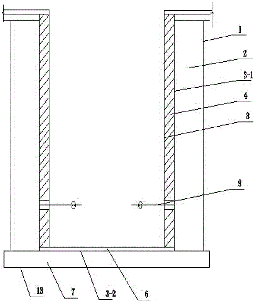
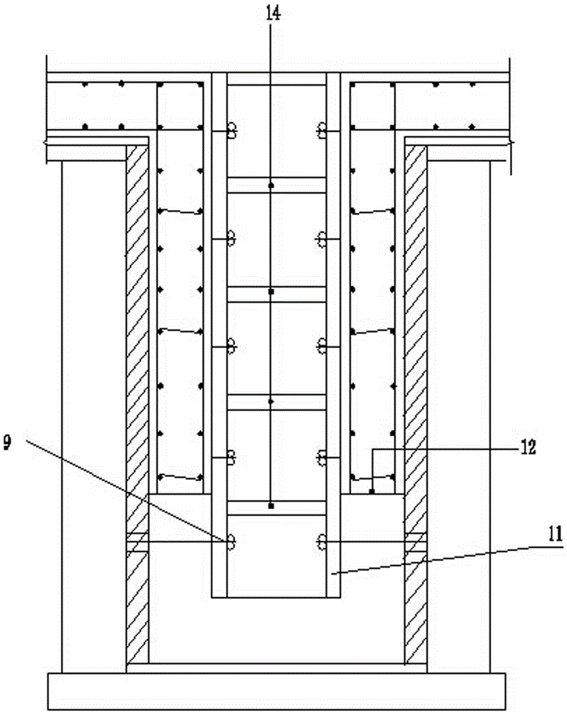
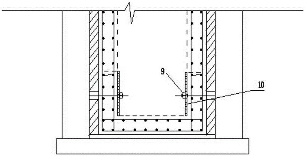
[0024] The present invention will be further described below in conjunction with the accompanying drawings.

[0025] see Figure 1-Figure 3 , a relatively deep elevator shaft or water collection well construction method, comprising the steps of:

[0026] Step 1. After the earthwork of the foundation pit of the elevator shaft or water collection well is completed, construct the bottom of the foundation pit

[0027] (1) Make the bottom backfill plain soil layer 13 at the bottom;

[0028] (2) Make a plain concrete reinforcement cushion 7 on the bottom backfill plain soil layer 13;

[0029] (3) Set the bottom waterproof membrane layer 3-2 on the plain concrete reinforced cushion layer 7;

[0030] (4) Make a fine stone concrete protective layer 6 on the bottom waterproof membrane layer 3-2;

[0031] Step 2: Construction of the side wall of the foundation pit

[0032] (1) Make the side wall plain concrete membrane 2;

[0033] (2) Symmetrical manual backfilling and layered tamp...


PUM


Abstract

The invention discloses a construction method for a deeper elevator well or a water collecting well. The construction method comprises the following steps that 1, after the foundation pit earthwork of the elevator well or the water collecting well is completed, the plain refilling, plain concrete reinforcing pad layer construction, bottom waterproof coil material layer construction and fine stone concrete protection layer construction are sequentially completed; 2, a side wall plain concrete blank is manufactured, the plain refilling is carried out outside the plain concrete blank in a laminated ramming way, a side wall waterproof coil material layer and a protection brick wall are sequentially arranged at the inner wall of the plain concrete blank, in addition, a water stop screw bolt is embedded in the protection brick wall, and a space surrounded by the protection brick wall and the fine stone concrete protection layer is a water collecting well pit; 3, in the water collecting well pit, the water stop screw bolt is used for binding steel bars for manufacturing a wall toe hanging mold template and an integral vertical mold template, the concrete is cast for completing the construction of the whole elevator well or the water collecting well. The construction method has the advantages that the waterproof layer damage due to submersible water seeping through the blank can be prevented, the waterproof capability is improved, in addition, the upward floating of the template can be prevented, and the construction quality of the concrete is improved.

Description

technical field [0001] The invention relates to the field of underground concrete structure construction, in particular to a construction method for a deep elevator shaft or a water collection shaft. Background technique [0002] In the construction of elevator shafts or water collection wells when the groundwater level is high, the conventional membrane waterproofing process cannot effectively curb the accumulation and infiltration of soil water around the brick tire membrane even with continuous precipitation, resulting in damage to the waterproof membrane; formwork installation Hanging formwork or integral cylinder formwork with bottom sealing is often used, which cannot completely solve the problem of "floating" of deep well formwork during the pouring process; deep well concrete pouring cannot be completed at one time, and construction cold joints are easy to form, and anti-leakage treatment is difficult; concrete Poor pumping and drainage of accumulated water during po...

Claims


Application Information

Patent Timeline
Patent Type & Authority Patents(China)
IPC IPC(8): E02D29/045E02D17/02
CPCE02D17/02E02D29/045
Inventor 郑涛桂祁东
Owner WUHAN YIYE CONSTR ENG
Learn More