Seal ring

A sealing ring, a technology in the circumferential direction, applied to the sealing of the engine, components with teeth, transmission control, etc., can solve the problems of oil leakage, leakage, etc., and achieve low leakage, reduce driving loss, and low friction.

Inactive Publication Date: 2015-02-18
RIKEN CO LTD
View PDF7 Cites 5 Cited by
  • Summary
  • Abstract
  • Description
  • Claims
  • Application Information

AI Technical Summary

Problems solved by technology

[0008] In the seal ring of Patent Document 1, the sliding contact between the side surface of the seal ring and the annular groove is line contact, and the sliding diameter is located on the joint gap of the seal ring, so there is a problem of oil leakage (leakage) from the joint gap.

Method used


Image

  • Seal ring
  • Seal ring
  • Seal ring

Examples


Embodiment 1

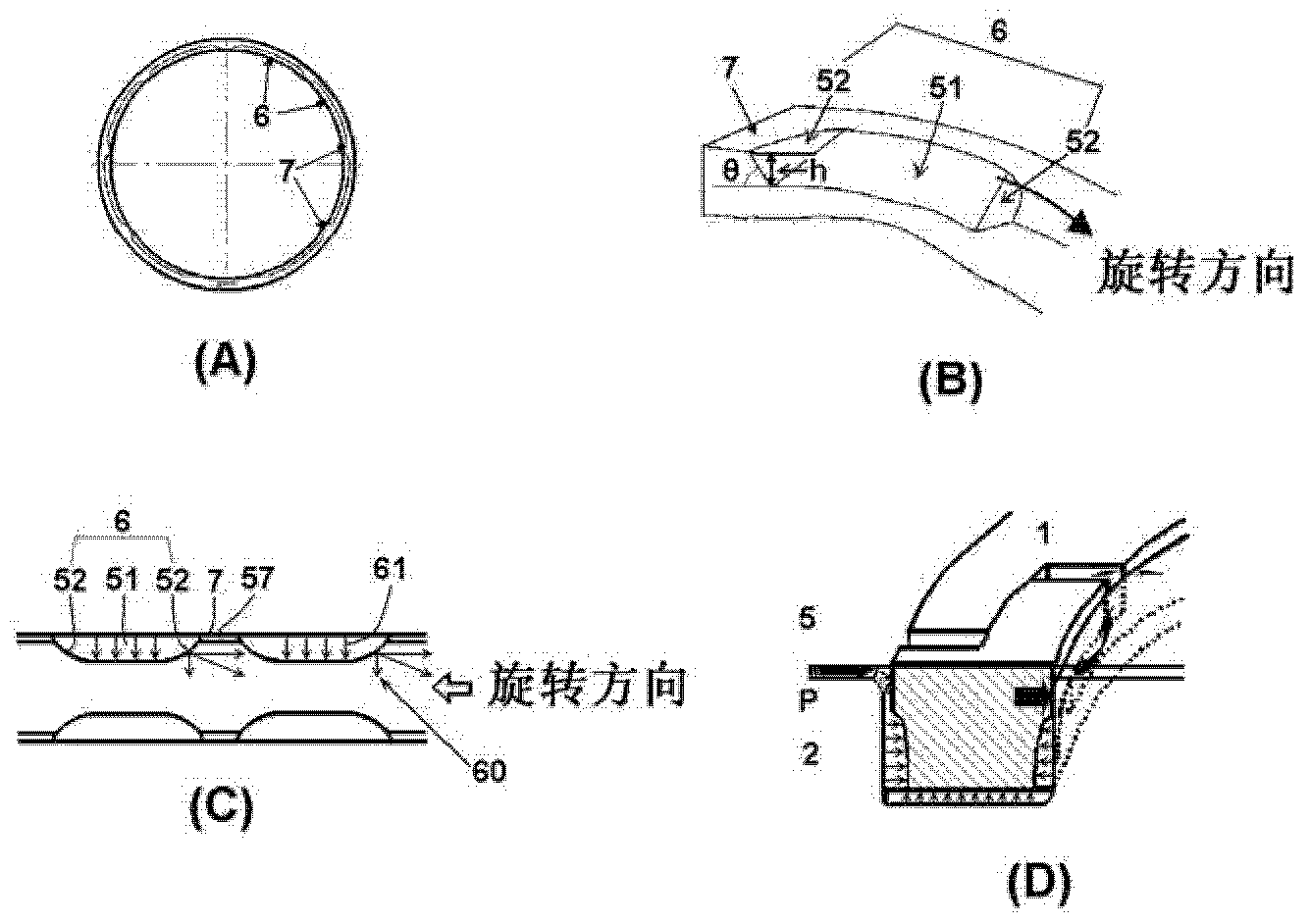
[0064] Using PEEK material with added carbon fiber, through injection molding, it has image 3 (A) A seal ring in the shape of a concave portion of the structure. Here, the slope angle θ of the concave portion was 16°, the depth h of the deepest slope portion 52 was 0.42 mm, and eight concave portions were formed on the contact side surface. An inner wall with a width of 0.3 mm and a circumferential length of 10 mm on one side was provided along the inner peripheral end from the front end in the circumferential direction of each recess toward the center, and an oil introduction hole with a circumferential length of 3 mm was formed in the center. It should be noted that the outer diameter (called diameter) of the sealing ring is 67mm, the thickness (radial width) is 2.3mm, the width (axial width) is 2.32mm, and the interface is Figure 6 The three-level ladder interface shown.

Embodiment 2

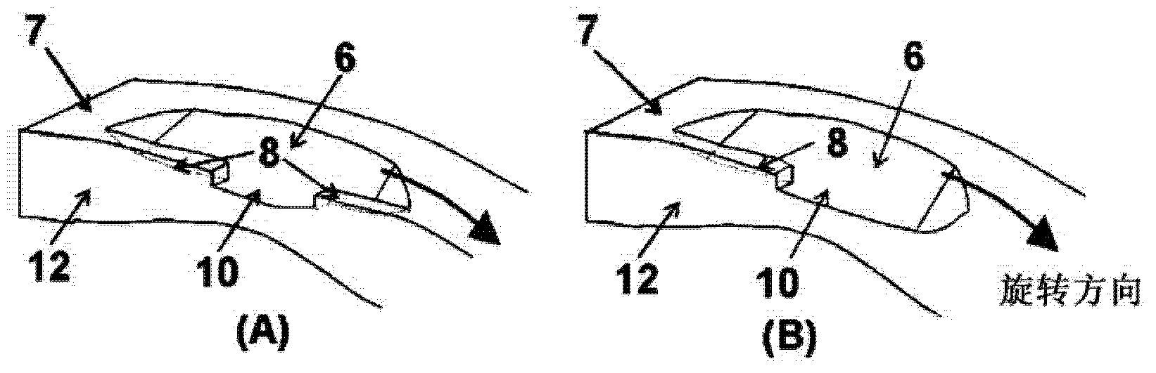
[0066] Using PEEK material with added carbon fiber, through injection molding, it has Figure 4 (A) A seal ring in the shape of a concave portion of the structure. Here, eight concavities having a curvature of the throttle portion of R40 and a depth of 0.22 mm at the deepest portion were formed. An inner wall with a width of 0.3 mm and a circumferential length of 10 mm on one side was provided along the inner peripheral end from both sides of each recess toward the center, and an oil introduction hole with a circumferential length of 3 mm was formed in the center. It should be noted that the outer diameter (called diameter) of the sealing ring is 67mm, the thickness (radial width) is 2.3mm, the width (axial width) is 2.32mm, and the interface is Figure 6 The three-level ladder interface shown.

Embodiment 3

[0068] Using PEEK material with added carbon fiber, through injection molding, it has Figure 5 (A) A seal ring in the shape of a concave portion of the structure. Here, eight concavities having a curvature of the throttle portion of R100 and a depth of 0.15 mm at the deepest portion were formed. An inner wall with a width of 0.3 mm and a length of 20 mm in the circumferential direction was provided along the inner peripheral end from the side opposite to the rotational direction of each recess, and an oil introduction hole with a length of 2 mm in the circumferential direction was formed on the rotational direction side. It should be noted that the outer diameter (called diameter) of the sealing ring is 67mm, the thickness (radial width) is 2.3mm, the width (axial width) is 2.32mm, and the interface is Figure 6 The three-level ladder interface shown.

[0069] (Measurement of Friction Force and Oil Leakage)

[0070] Such as Figure 7As shown, the seal rings of Examples 1 ...


PUM


Abstract

Provided is a seal ring that has low-leakage characteristics and low-friction characteristics and can improve the drive loss of the automatic transmission of an automobile to thereby contribute to an improvement in the fuel consumption of the automobile. The seal ring is attached to a shaft groove formed on the outer peripheral surface of a shaft. A plurality of peripherally spaced recessed sections are formed on at least the inner peripheral side of a contact side-surface. Inner walls are provided on the inner peripheral side of the recessed sections, and oil introduction openings that open on an inner peripheral surface are provided on the inner peripheral side of the recessed sections. The inner walls may be provided on opposite peripheral sides of the recessed sections but may be provided only on the rear side in the rotation direction.

Description

[0001] This application is a divisional application of the application with the application number 201180026486.0 and the invention name "Sealing Ring" submitted on November 28, 2012. technical field [0002] The present invention relates to a seal ring, and in particular to a seal ring used in hydraulic equipment such as an automatic transmission of a motor vehicle. Background technique [0003] In recent years, in order to improve the fuel efficiency of automobiles, it is required to reduce the driving loss of automatic transmissions. A seal ring is attached to the automatic transmission for the purpose of hydraulic sealing, but frictional loss of the seal ring causes a driving loss of the automatic transmission. Therefore, reduction of the frictional force of the seal ring has become an important issue. Furthermore, since the capacity of the oil pump of an automatic transmission accounts for a large proportion of the driving loss, it is desired to reduce the amount of oi...

Claims


Application Information

Patent Timeline
Patent Type & Authority Applications(China)
IPC IPC(8): F16J15/18F16H57/029
CPCF16H2061/0046F16J15/16F16J15/441
Inventor 永井纯也柴野知哉齐藤美香
Owner RIKEN CO LTD
Why Eureka
Try Eureka