
Method for configuring power distribution reactive and comprehensive control strategies and optimal capacity

A technology of capacity allocation and comprehensive control, which is applied in reactive power compensation, circuit devices, reactive power adjustment/elimination/compensation, etc., can solve problems such as unsatisfied action conditions, poor operating status, uncontrollable equipment, etc., to achieve the best The effect of optimizing reactive power distribution, realizing reactive power distribution, and improving voltage qualification rate

Active Publication Date: 2015-02-18
STATE GRID CORP OF CHINA +1
View PDF4 Cites 6 Cited by
  • Summary
  • Abstract
  • Description
  • Claims
  • Application Information

AI Technical Summary

Problems solved by technology

[0004] 1) The distribution network has many points and a wide range of load types, and there are few operational monitoring data available. The traditional method of unified modeling and calculation of the entire network has a large amount of calculation, and the algorithm is complex and time-consuming.
[0005] 2) The equipment with poor operating status can only improve its operating status through the actions of related equipment in the adjacent power grid because it is uncontrollable or does not meet the operating conditions.
For example, for no-load voltage regulation and distribution transformer, when the voltage is lower limit, the voltage level can only be improved through line voltage regulator or main transformer voltage regulation
[0006] 3) After the control command is executed, due to the correlation between different voltage levels and regional power grids, it is easy to take care of one thing and lose another.
For example, if the main transformer lowers the voltage, although it can adjust the voltage of the distribution transformer whose voltage is higher than the upper limit, but at the same time, it may cause the original voltage of the distribution transformer to be lower than the lower limit.
[0007] 4) The action of the equipment must be based not only on the local measurement information, but also on the coordination request of the upper and lower power grids, which may easily cause oscillations in the action of the equipment
If the voltage of the users in the low-voltage station area is low, request the distribution transformer to increase the voltage, but the increase may cause the local voltage of the distribution transformer to exceed the upper limit

Method used


Image

  • Method for configuring power distribution reactive and comprehensive control strategies and optimal capacity
  • Method for configuring power distribution reactive and comprehensive control strategies and optimal capacity

Examples


Embodiment Construction

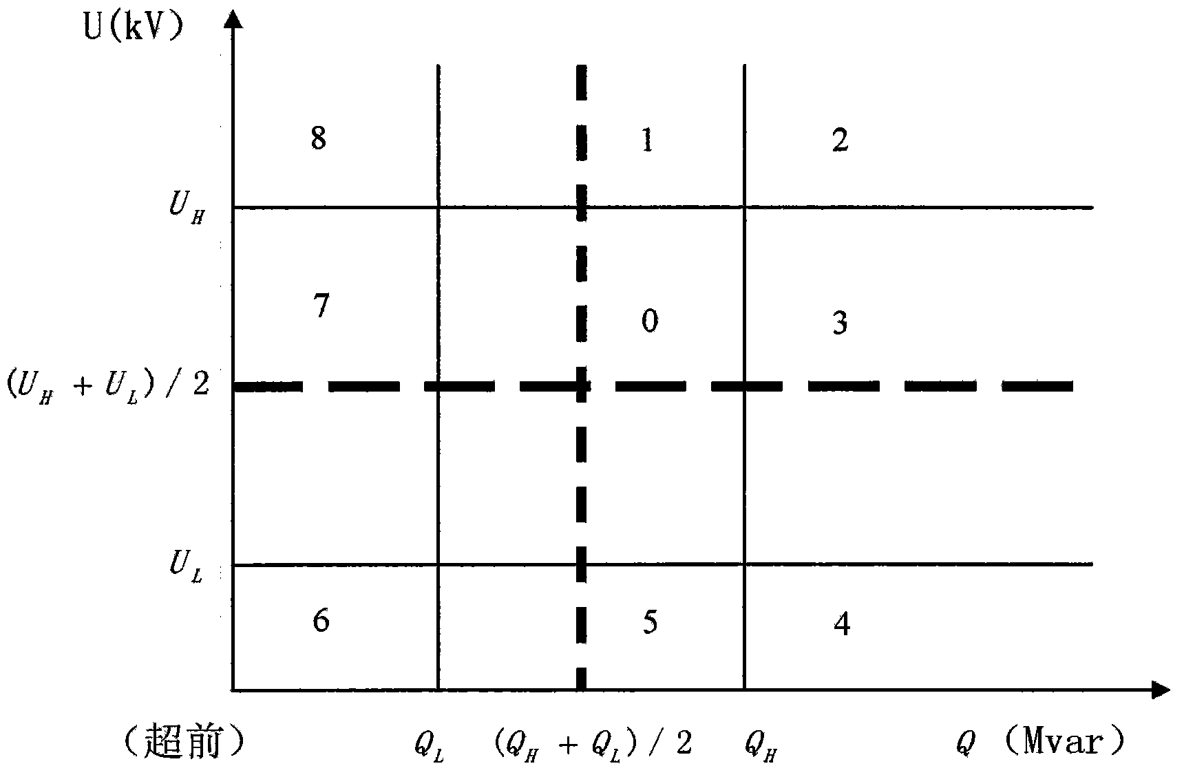
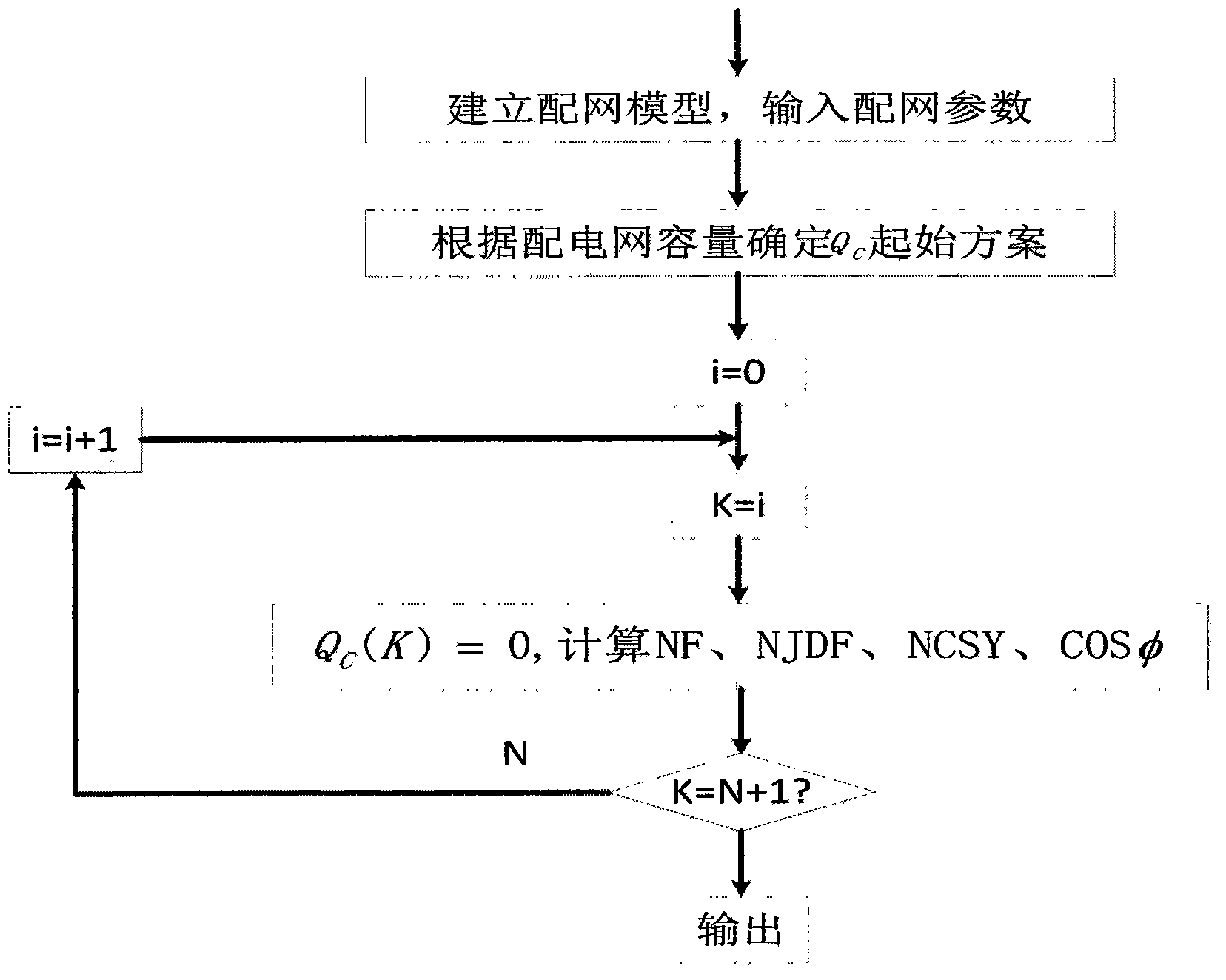
[0047] The comprehensive reactive power distribution control strategy and optimal capacity configuration method of the present invention will be further described in detail below in conjunction with the accompanying drawings and the embodiments of the present invention.

[0048] The principle followed by the comprehensive control strategy of distribution voltage and reactive power control and the optimal reactive power capacity configuration method of distribution network in the present invention is as follows:

[0049] 1) Adjust the reactive power first, and then adjust the voltage. Reactive power balance is the basic condition for power transmission, conversion and maintenance of normal operation of electrical equipment. At the same time, it can be seen from the reactive voltage characteristic curve that when the load changes, in order to maintain the reactive power balance, a new reactive power balance point will inevitably be formed, resulting in changes in the operating v...


PUM


Abstract

The invention discloses a method for configuring power distribution reactive and comprehensive control strategies and the optimal capacity. The method includes steps of A, automatically controlling voltage reactive optimal combinations; B, configuring and computing the power distribution reactive control optimal capacity. The method has the advantages that difficulty in voltage reactive control on current power distribution networks is comprehensively considered by the aid of the method, accordingly, the power distribution voltage and reactive and comprehensive control strategies and the reactive optimal capacity of the power distribution networks can be configured, and the power supply ability of the power distribution networks can be improved.

Description

technical field [0001] The present invention relates to distribution network reactive power optimization technology, in particular to a power distribution reactive power comprehensive control strategy and optimal capacity configuration method, which is suitable for distribution network voltage and reactive power comprehensive control, optimal capacity configuration and distribution network energy efficiency assessment. Background technique [0002] Traditional voltage and reactive power control is mostly local automatic control. By monitoring local voltage, active power, and reactive power, adjusting the transformer gear or capacitor switch makes the voltage and reactive power within the acceptable range. [0003] At present, almost all the researches on control methods and strategies only focus on the substation level and above power grids, and there are few studies on 10kV and below power grids. Since the automation and intelligence of the distribution network is far lowe...

Claims


Application Information

Patent Timeline
Patent Type & Authority Applications(China)
IPC IPC(8): H02J3/16H02J3/18
CPCH02J3/16H02J3/1864Y02E40/30
Inventor 吕志来喻宜张东王云鹏张学深李海
Owner STATE GRID CORP OF CHINA
Learn More