Single-phase electric energy quality controller for electrified railway power supply system
A technology for electrified railways and power supply systems, applied in the directions of reducing the asymmetry of polyphase networks, eliminating/reducing asymmetry in polyphase networks, reducing harmonics/ripples in AC networks, etc. Limit application and other issues to achieve the effect of improving power quality problems, reducing costs and operating losses, and reducing system losses
- Summary
- Abstract
- Description
- Claims
- Application Information
AI Technical Summary
Problems solved by technology
Method used
Image
Examples
example 1
[0032] Example 1: Hybrid UPQC in the same phase power supply system based on V, v transformer
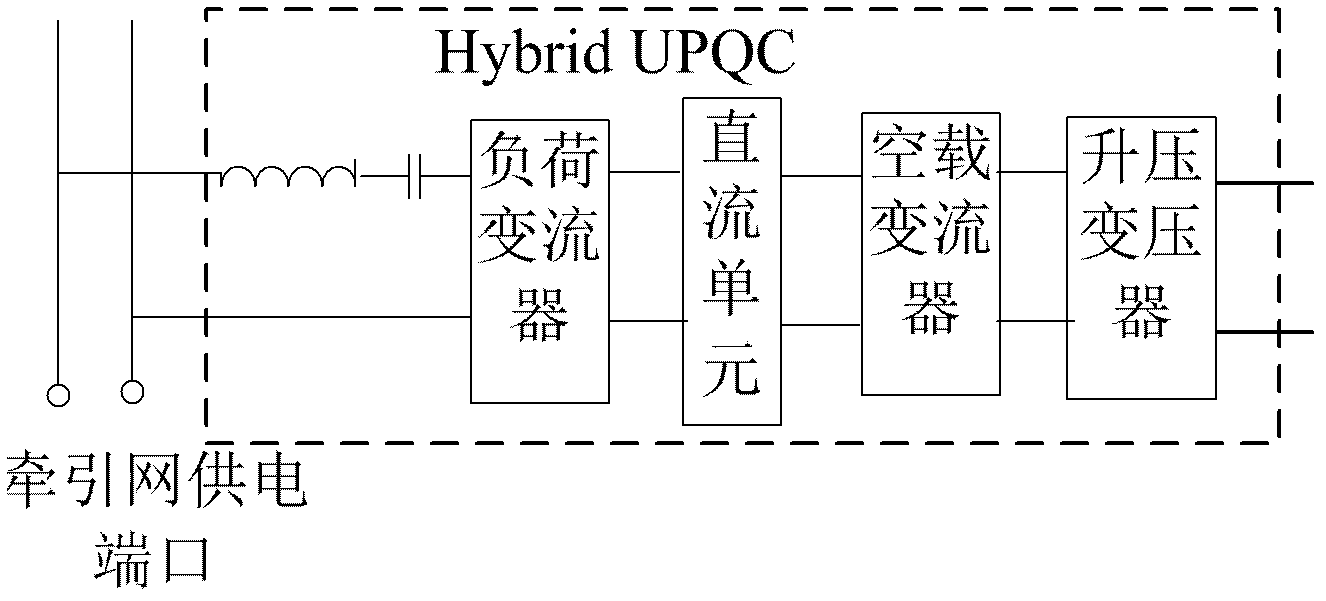
[0033] In this embodiment, the Hybrid UPQC is installed in a traction substation using a V, v transformer to realize the same-phase power supply system. The detailed schematic diagram of the same-phase power supply system is as follows Figure 6 shown.
[0034] Assume that the public grid, that is, the three-phase voltage on the primary side of the traction transformer is as follows:
[0035]
[0036] In the above formula, V represents the effective value of the phase voltage of the three-phase power supply system connected to the traction substation.
[0037] Such as Figure 4 In the wiring, V, v transformer secondary side voltage is as follows:
[0038]
[0039] In the above formula, v α and v β Represent V, v the output voltage of the secondary side of the transformer, where v α Directly supply power to the traction network, v β is the no-load side in the non-inverti...
example 2
[0065] Example 2: Hybrid UPQC in the same-phase power supply system based on single-phase transformers
[0066] This example is basically the same as Example 1, except that the traction substation uses a single-phase transformer to supply power to the traction network, the load-side converter of the Hybrid UPQC is still connected to the traction network, and the no-load side converter is connected to the traction network through a step-up transformer. into the other two phases of the system, such as Figure 7 shown. Assuming that the traction substation is connected to the 110kV public grid, the DC voltage of the inverter is set to 28kV, the inductance and capacitance in the capacitive impedance resonate at the fifth harmonic, and the transformation ratio of the step-up transformer connected to the no-load side converter is Revised to 1:5.5.
PUM
 Abstract
Description
Claims
Application Information
 - R&D
- Intellectual Property
- Life Sciences
- Materials
- Tech Scout
- Unparalleled Data Quality
- Higher Quality Content
- 60% Fewer Hallucinations
Browse by: Latest US Patents, China's latest patents, Technical Efficacy Thesaurus, Application Domain, Technology Topic, Popular Technical Reports.
© 2025 PatSnap. All rights reserved.Legal|Privacy policy|Modern Slavery Act Transparency Statement|Sitemap|About US| Contact US: help@patsnap.com


