filter direct synthesis method

A comprehensive method and filter technology, applied in the field of signal processing, can solve the problems that filters cannot achieve complex frequency response and lack of realization structure

Inactive Publication Date: 2017-04-12
肖飞
View PDF4 Cites 0 Cited by
  • Summary
  • Abstract
  • Description
  • Claims
  • Application Information

AI Technical Summary

Problems solved by technology

[0003] The purpose of the present invention is to solve the shortcomings in the prior art that the filter cannot realize the complex frequency response and the lack of flexibility in the realization structure, and proposes a filter direct synthesis method

Method used


Image

  • filter direct synthesis method
  • filter direct synthesis method
  • filter direct synthesis method

Examples


Embodiment 1

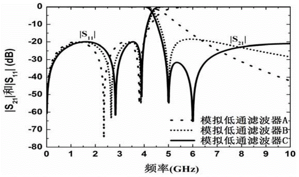
[0113] Embodiment 1 is about the synthesis of analog low-pass filters. Here, three analog low-pass filters are taken as an example, namely, analog low-pass filter A, analog low-pass filter B, and analog low-pass filter C. The pass-band cut-off frequencies of the three analog low-pass filters are all set to 4GHz, and the return loss in the pass-band is less than -20dB. In order to illustrate the superiority of the method of the present invention, that is, the performance of the analog low-pass filter can be changed by setting the transmission zero point at the specified position, so that it can flexibly meet the requirements. Three analog low-pass filters have different frequency responses ,like figure 2 shown. In the analog low-pass filter A, all transmission zeros can be placed at infinity, resulting in good high-frequency rejection. Its filter polynomial is as follows:

[0114]

[0115]

[0116]

[0117] The transmission matrix can be derived from these filter p...

Embodiment 2

[0131] The second embodiment is about the synthesis of analog high-pass filters. For example, to design an analog high-pass filter, the initial frequency of its passband is specified as 5GHz, the return loss in the passband is lower than -20dB, one transmission zero is located at zero frequency, and the other transmission zero is set at 2GHz, its frequency response like Image 6 shown. By method described in the present invention, can derive the filtering polynomial of analog high-pass filter as follows:

[0132]

[0133]

[0134]

[0135] The transmission matrix can be derived from these filter polynomials, so as to obtain its circuit realization network, such as Figure 7 shown. Figure 7 The component values ​​in are as follows:

[0136] R S = R L =50Ω, L 1 =2.1477nH, L 2 =9.0781nH, C 2 =0.6976pF,L 3 = 2.1477nH.

[0137] In addition, in Figure 8 Its dual network is given in . Figure 8 The component values ​​in are as follows:

[0138] R S = R L = ...

Embodiment 3

[0139] The third embodiment is about the synthesis of analog bandpass filters. For example, to synthesize a third-order analog bandpass filter, its passband is located at [3.0, 5.0]GHz, the return loss in the passband is lower than -20dB, a transmission zero is located at zero frequency, and a transmission zero is located at 2.5GHz, A transmission null is located at 6.0GHz. These transmission zeros at finite frequencies can improve the frequency selectivity of the filter, whose frequency response is as Figure 9 shown. By method described in the present invention, can derive the filtering polynomial of this analog bandpass filter as follows:

[0140]

[0141]

[0142]

[0143] The transmission matrix can be derived from these filter polynomials, so as to obtain its circuit realization network, such as Figure 10 shown. Figure 10 The component values ​​in are as follows:

[0144] R S = R L =50Ω, L 1 =2.9570nH, L 2 = 1.1561nH, C 2 =3.5057pF, L 3 =0.8761nH,C ...


PUM


Abstract

The invention discloses a filter direct synthetic method. By means of the filter direct synthetic method, the transmission zero points of filters can be flexible arranged, a smoothing polynomial of the filters can be led out, and the smoothing polynomial includes all information of the filters and can be directly used for achieving the filters. Effective connection is conduced through some basic structures which can achieve one or more transmission zero points, an achieving network of the filters is finally obtained, and modularization synthesis can be achieved; the method can be used for designing digital filters through bilinear transformation; the types of the filters comprise the low-pass type, the high-pass type, the band-pass type, the band elimination type and the like. The filter direct synthetic method has the advantages of being simple, fast and accurate.

Description

technical field [0001] The invention belongs to the technical field of signal processing, and in particular relates to the design of a filter direct synthesis method. Background technique [0002] The filter is one of the key components in radar, communication and measurement systems. Its function is to allow the signal of a certain frequency to pass smoothly, while allowing the signal of another part of the frequency to be greatly suppressed. Its performance is important to the performance of the entire system. Impact. Modern radar, communication and measurement systems usually require filters with good frequency selectivity and other characteristics. Divided according to the working object, filters can be divided into two categories: analog filters and digital filters. Analog filters are used to process analog or continuous-time signals, and can be divided into lumped parameter or distributed parameter filters; in addition, according to the type of components used, analo...

Claims


Application Information

Patent Timeline
Patent Type & Authority Patents(China)
IPC IPC(8): H03H17/02
Inventor 肖飞唐萍
Owner 肖飞
Why Eureka
Try Eureka