Method for manufacturing steel plate shear wall and temporary supporting structure for steel plate shear wall

A steel plate shear wall and temporary support technology, applied in the direction of walls, building components, manufacturing tools, etc., can solve the problems of poor precision control, high difficulty of welding and assembly, and increase the difficulty of welding and assembly precision control, so as to avoid Distortion, the effect of improving precision

Active Publication Date: 2015-02-25
CHINA CONSTR STEEL STRUCTURE ENG CO LTD
View PDF4 Cites 6 Cited by
  • Summary
  • Abstract
  • Description
  • Claims
  • Application Information

AI Technical Summary

Problems solved by technology

Due to the long length of the steel plate, both the box-shaped column and the steel plate are large-scale components. Therefore, it is difficult to accurately position the steel plate and the box-shaped column during welding, resulting in greater difficulty in welding and assembly

Method used


Image

  • Method for manufacturing steel plate shear wall and temporary supporting structure for steel plate shear wall
  • Method for manufacturing steel plate shear wall and temporary supporting structure for steel plate shear wall
  • Method for manufacturing steel plate shear wall and temporary supporting structure for steel plate shear wall

Examples


Embodiment Construction

[0029] In order to make the technical problems, technical solutions and beneficial effects to be solved by the present invention clearer, the present invention will be further described in detail below in conjunction with the accompanying drawings and embodiments. It should be understood that the specific embodiments described here are only used to explain the present invention, not to limit the present invention.

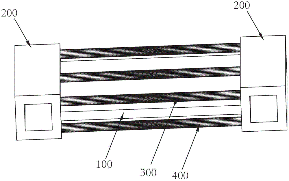
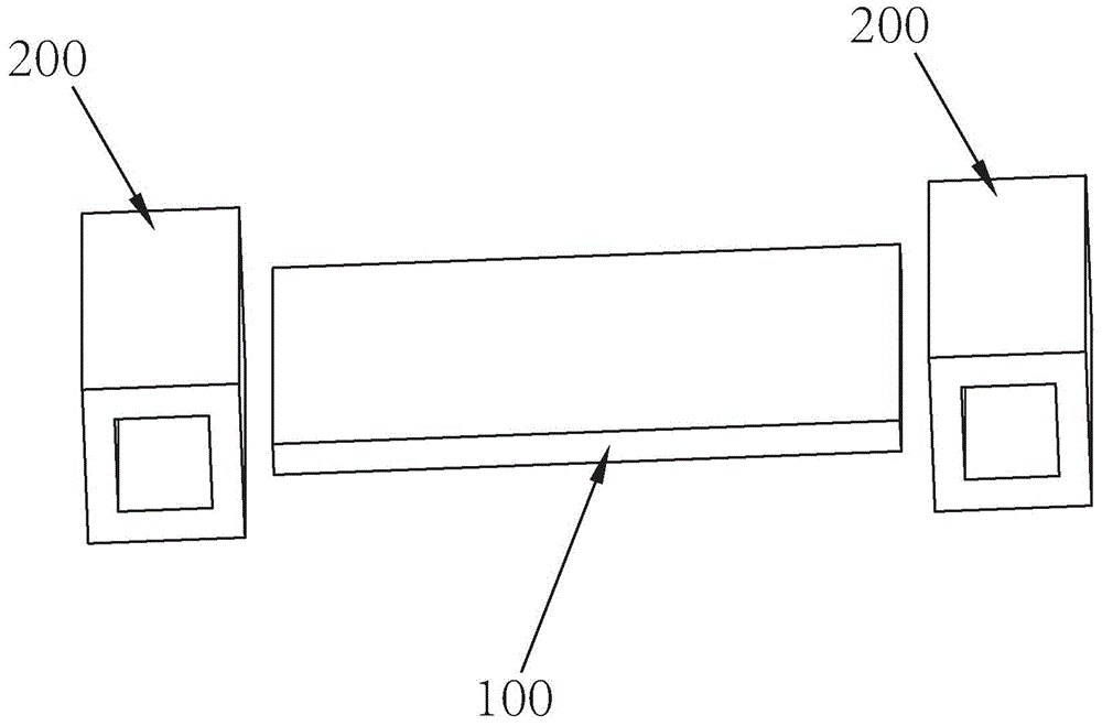
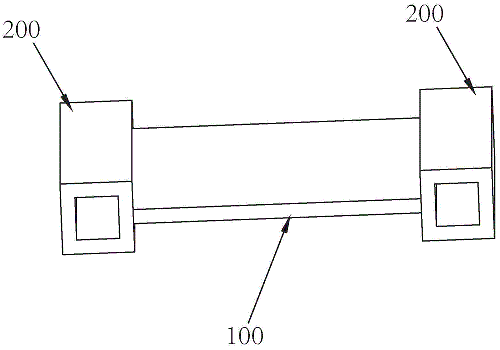
[0030] like figure 1 Shown is a preferred embodiment of the temporary support structure of the steel plate shear wall of the present invention, including a steel plate 100 , two box columns 200 , a first support column 300 and a second support column 400 .

[0031] The two ends of the steel plate 100 are welded and fixed on the sides of the two box-shaped columns 200, the first support column 300 and the second support column 400 are symmetrically distributed above and below the steel plate 100, and the first and second support columns 300, 400 Both ends of each a...


PUM


Abstract

The invention relates to a method for manufacturing a steel plate shear wall and a temporary supporting structure for the steel plate shear wall. The temporary supporting structure for the steel plate shear wall comprises a steel plate, two box-shaped columns, a first supporting column and a second supporting column, wherein the two ends of the steel plate are welded and fixed to the side faces of the two box-shaped columns, the first supporting column and the second supporting column are symmetrically distributed above and below the steel plate, the two ends of the first supporting column are fixed to the two box-shaped columns respectively, and the two ends of the second supporting columns are fixed to the two box-shaped columns respectively. According to the method for manufacturing the steel plate shear wall and the temporary supporting structure for the steel plate shear wall, assembly positioning lines used for assembly of the steel plate are marked on the side faces of the box-shaped columns, the two box-shaped columns can be fixed in advance through the first supporting column and the second supporting column during welding, and thus the steel plate and the two box-shaped columns can be positioned conveniently; in addition, welding crevasses of the steel plate can be firmly in butt joint with welding crevasses of the box-shaped columns, deviation caused by deformation of the thin steel plate is reduced, and both welding precision and assembling precision are improved.

Description

technical field [0001] The invention belongs to the field of building construction, and in particular relates to a manufacturing method of a steel plate shear wall and a temporary support structure thereof. Background technique [0002] The steel plate shear wall structure is a new type of lateral force-resisting structural system developed in the 1970s. As a new type of lateral force-resisting member, the steel plate shear wall structure system has the characteristics of large elastic initial stiffness, large deformation capacity, good plastic performance, and stable hysteretic characteristics. [0003] The steel plate shear wall structure generally includes a steel plate and box columns on both sides of the steel plate, and the two ends of the steel plate are welded and fixed on the two box columns. Due to the long length of the steel plate, the box-shaped column and the steel plate are both large-scale components. Therefore, it is difficult to accurately position the ste...

Claims


Application Information

Patent Timeline
IPC IPC(8): B23K31/02B23K37/00B23K37/04B23P15/00
CPCB23K31/02B23K37/0426B23P15/00E04B2/56
Inventor 戴立先陈韬廖选茂李春田周茂臣陈小飞张阳李任戈孙伟
Owner CHINA CONSTR STEEL STRUCTURE ENG CO LTD
Why Eureka
Try Eureka