Finishing equipment and method for spherical sapphire

A sapphire and spherical technology, which is applied in the field of spherical sapphire finishing equipment, can solve the problems of high inconsistent rate of outer diameter, lower qualified rate of finished products, and low production efficiency, so as to avoid random rolling and mutual collision, improve the qualified rate of finished products, The effect of improving productivity

Inactive Publication Date: 2018-02-02
ZHENJIANG JINLAIBAO OPTOELECTRONICS CO LTD
View PDF6 Cites 0 Cited by
  • Summary
  • Abstract
  • Description
  • Claims
  • Application Information

AI Technical Summary

Problems solved by technology

[0004] The finishing equipment of the prior art spherical sapphire has the following problems and deficiencies in actual use: because the material-grade spherical sapphire is rotated at a low speed by an agitator in a fixed grinding pot with the participation of an appropriate amount of green silicon carbide micropowder and water Driven and randomly rolled, the opportunity for each material-grade spherical sapphire to be stirred to produce a grinding effect is random and irregular, so the outer diameter of each material-grade spherical sapphire ground into the pot in the same batch is inconsistent. High, the error range of the outer diameter of the measured ball diameter to meet the process requirements can only be about 30% of the number of all material-grade spherical sapphires put into the pot in the same batch, that is, the qualified rate of finished products is low; The low-speed rotation in the moving grinding pot drives each material-grade spherical sapphire to roll randomly, which will inevitably cause random collisions on the surface of each material-grade spherical sapphire, and the surface of the processed material-grade spherical sapphire will also be affected by the rotating agitator. Random collision, such two random collisions cause surface scars on the finished spherical sapphire, which affects the improvement of the pass rate of the surface finish. Become a qualified product, which further causes the finished product qualified rate of the finishing equipment and method of using the spherical sapphire of the prior art to reduce, thereby resulting in low production efficiency and high cost

Method used


Image

  • Finishing equipment and method for spherical sapphire
  • Finishing equipment and method for spherical sapphire

Examples


Embodiment 1

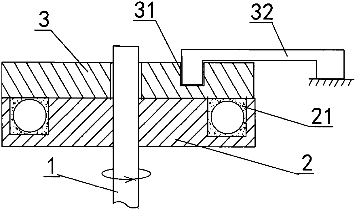
[0026] Embodiment 1: as figure 1 As shown, a finishing equipment for spherical sapphire is characterized in that it is a finishing equipment for spherical sapphire, which is characterized in that it includes a low-speed rotating shaft 1, a rotary groove disc 2 fixed on the upper end of the low-speed rotating shaft and passing through the low-speed rotating shaft. The upper end of the shaft is crimped on the fixed pressure plate 3 above the rotary groove plate. The rotating speed of the low-speed rotating shaft 1 is 95 rpm. The rotary groove plate 2 is provided with an annular groove 21 whose width and depth are slightly larger than the ball diameter 10mm required by the processed spherical sapphire technology. 50 times the diameter. Said rotary groove disc 2 is provided with a width and a depth slightly larger than the ball diameter of the processed spherical sapphire. The slightly larger in the annular groove 21 means that the width and depth of the annular groove are larg...

Embodiment 2

[0031] Embodiment 2: as figure 1 As shown, a finishing equipment for spherical sapphire is characterized in that it is a finishing equipment for spherical sapphire, which is characterized in that it includes a low-speed rotating shaft 1, a rotary groove disc 2 fixed on the upper end of the low-speed rotating shaft and passing through the low-speed rotating shaft. The upper end of the shaft is crimped on the fixed pressure plate 3 above the rotary groove plate. The rotating speed of the low-speed rotating shaft 1 is 100 rpm. Said rotary groove disc 2 is provided with an annular groove 21 whose width and depth are slightly larger than the ball diameter 4mm required by the processed spherical sapphire technology, and the central ring arc length of the annular groove is slightly larger than the processed spherical sapphire technology required ball. 100 times the diameter. Said rotary groove disc 2 is provided with a width and a depth slightly larger than the ball diameter of th...

Embodiment 3

[0036] Embodiment 3: as figure 1 As shown, a finishing equipment for spherical sapphire is characterized in that it is a finishing equipment for spherical sapphire, which is characterized in that it includes a low-speed rotating shaft 1, a rotary groove disc 2 fixed on the upper end of the low-speed rotating shaft and passing through the low-speed rotating shaft. The upper end of the shaft is crimped on the fixed pressure plate 3 above the rotary groove plate. The rotational speed of the low-speed rotating shaft 1 is 105 rpm. Said rotary groove disc 2 is provided with an annular groove 21 whose width and depth are slightly larger than the ball diameter 2mm required by the processed spherical sapphire technology, and the central ring arc length of the annular groove is slightly larger than the processed spherical sapphire technology required ball. 200 times the diameter. Said rotary groove disc 2 is provided with a width and a depth slightly larger than the ball diameter of ...


PUM


Abstract

The invention relates to a spherical sapphire finish machining device and method, and belongs to sapphire machining devices and methods. The spherical sapphire finish machining device comprises a low speed rotating shaft, a rotary groove disc fixed to the upper end of the low speed rotating shaft and a fixed pressing disc connected to the rotary groove disc in a pressed mode. The spherical sapphire finish machining method is characterized by including the steps of A, a material preparation process, wherein sapphire materials are roughly machined to enable the actually-measured sphere diameter to range from 8% to 15% of the sphere diameter required by the technology; B, a material loading process, wherein N material-level spherical sapphires are annularly arranged in an annular groove of the rotary groove disc of the spherical sapphire finish machining device, an appropriate amount of green silicon carbide micro powder or silicon carbide and an appropriate amount of water are added, and finally the fixed pressing disc is connected to the rotary groove disc in the pressed mode; C, a grinding process, wherein the device is started to drive the N material-level spherical sapphires in the annular groove to achieve the grinding effect. After the sapphires are tried out, the percent of pass of the made-up spherical sapphires is stabilized to be higher than 90% by means of the spherical sapphire finish machining device and method; compared with the prior art, the percent of pass of the made-up spherical sapphires is improved by more than three times in a stabilized mode.

Description

technical field [0001] The invention relates to a processing equipment and method for sapphire, in particular to a finishing equipment and method for spherical sapphire. Background technique [0002] Sapphire crystal has good light transmission performance, and its light transmission range is 0.15-7.5 microns, covering ultraviolet, visible, near-infrared, mid-infrared and other bands; the melting point is as high as 2045 ° C, and the working temperature can reach 1900 ° C. It also has excellent Excellent mechanical properties and good radiation resistance and electrical insulation properties. Therefore, spherical sapphire is widely used in various optical fiber transmission and sensing systems. There are two main methods for processing and forming the existing sapphire spherical surface: 1) processing and forming with a special spherical forming machine tool, and its disadvantages are as follows: only sapphire spherical surfaces of specific sizes can be processed, and the u...

Claims


Application Information

Patent Timeline
Patent Type & Authority Patents(China)
IPC IPC(8): B24B37/025
CPCB24B37/025
Inventor 田洪军蔡志明邹宇琦田原贾培庆
Owner ZHENJIANG JINLAIBAO OPTOELECTRONICS CO LTD
Why Eureka
Try Eureka