
Shaft-simulating multifunctional flowing test system

A multifunctional testing and simulating wellbore technology, applied in measurement, wellbore/well components, earthwork drilling and production, etc., can solve problems such as inability to make full use of simulated string equipment, inability to inject liquid, and difficult adjustment of wellbore size parameters

Inactive Publication Date: 2015-02-25
CHINA UNIV OF PETROLEUM (BEIJING)
View PDF5 Cites 17 Cited by
  • Summary
  • Abstract
  • Description
  • Claims
  • Application Information

AI Technical Summary

Problems solved by technology

However, the existing wellbore multiphase flow, rock breaking, sand carrying, jet fracturing and other drilling and completion test devices have the following deficiencies: 1. The center pipe cannot rotate or move axially, and cannot simulate wellbore pressure fluctuations and pressure fluctuations under complex working conditions. 2. The impact of fractures in the formation on the flow law of the wellbore is not considered, and the impact on sand washing and sand-carrying processes in the presence of formation filtration cannot be simulated; 3. The wellbore size parameters are not easy to adjust, and the The rock-carrying laws of tiny boreholes and conventional wellbores cannot be compared effectively by experiments; 4. The annulus cannot be injected with fluid, and the wellbore flow laws of construction processes such as backwashing and hydraulic jet fracturing cannot be simulated; 5. The extension ability of equipment is poor and cannot fully Multiple drilling and completion tests using simulated string equipment

Method used


Image

  • Shaft-simulating multifunctional flowing test system
  • Shaft-simulating multifunctional flowing test system

Examples


Embodiment Construction

[0025] In order to have a clearer understanding of the technical features, purposes and effects of the present invention, the specific implementation manners of the present invention will now be described with reference to the accompanying drawings.

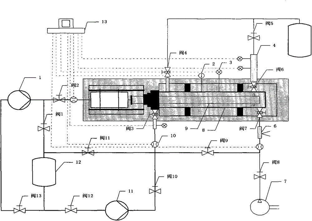
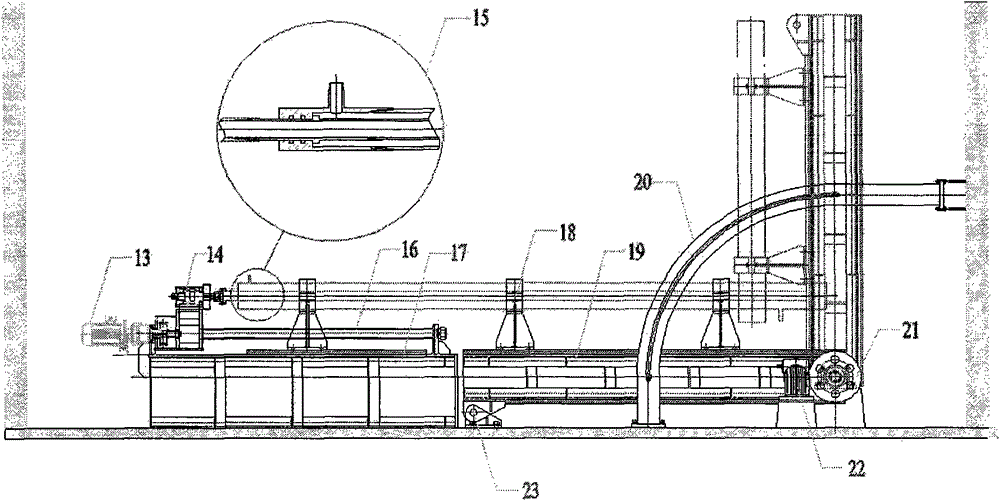
[0026] like figure 1 , figure 2 As shown, the multifunctional wellbore simulation test device mainly includes a liquid storage tank 12, a plunger pump 1 connected to the center pipe, a plunger pump 11 connected to the annular space, an electric motor 14 for controlling axial movement and rotation, and a Central pipe 15 for hydraulic swivel tap, small wellhead device 24, high-strength glass casing 8, central pipe for simulating oil pipe 9, crack simulator 4 for simulating crack existence, air compressor 7 for simulating formation gas intrusion, control data acquisition and processing Data controller 13, waste liquid tank 11, several flow, temperature, pressure sensors such as devices such as 2, 3, 10. Among them, the plunger pu...


PUM


Abstract

The invention relates to the field of petroleum drilling and completion technology tests, and discloses a shaft-simulating multifunctional test experimental device which mainly consists of such instruments as a shaft-simulating multifunctional test bed, a plunger pump, a data controller, an air compressor, a liquid storage tank and a waste liquid tank. The shaft-simulating multifunctional test bed revolves and axially moves through a center pipe, and can test the sand carrying capacity of a rotary sand flushing technology of a horizontal well; annular multi-phase flow parameters of a vertical well, an inclined well and a horizontal well can be observed through a lifting bracket of 0-90 degrees; the conventional or micro borehole drilling and completion experimental simulation can be performed through changing the size of a shaft; a crack simulator is combined to perform the test verification for hydraulic jet fracturing seal and in-hole boost mechanisms; and a pulse jet device can be combined to test a pulse jet flow field. The shaft-simulating multifunctional flowing test system is wide in purpose, is convenient and efficient, and can develop such multiple drilling and completion fluid experimental researches as rotary sand flushing, shaft multi-phase flow, hydraulic jet fracture and pulse jet.

Description

technical field [0001] The invention relates to the field of oil and natural gas drilling and completion technology tests, in particular to a drilling and completion fluid experiment capable of simulating multiphase flow in any angle wellbore, rotary sand washing in horizontal wells, hydraulic jet fracturing and pulse jet flow, etc. multifunctional test device. Background technique [0002] With the development trend of my country's oil and gas exploration and development towards deep formations, the law of multiphase flow in the wellbore under complex working conditions, efficient rock breaking, rock carrying, and fracturing mechanisms have increasingly become the focus and difficulty of research in the field of oil drilling and completion technology. Therefore, it is of great significance to predict and control construction parameters such as displacement, temperature, and pressure during drilling and completion by combining basic theory with drilling and completion experi...

Claims


Application Information

Patent Timeline
Patent Type & Authority Applications(China)
IPC IPC(8): E21B47/00E21B49/08
CPCE21B47/00E21B49/08
Inventor 李根生史怀忠黄中伟田守嶒宋先知王海柱陆沛青
Owner CHINA UNIV OF PETROLEUM (BEIJING)
Features
  • Generate Ideas
  • Intellectual Property
  • Life Sciences
  • Materials
  • Tech Scout
  • Unparalleled Data Quality
  • Higher Quality Content
  • 60% Fewer Hallucinations
Learn More