Spacecraft ontrack leakage orientation method

A spacecraft and sensor array technology, applied in the direction of detecting the appearance of fluid at the leak point, using liquid/vacuum degree for liquid tightness measurement, etc., can solve the problems that cannot meet engineering needs, unstable orientation results, complex noise, etc. , achieve high orientation accuracy and stability, improve orientation accuracy and stability, and overcome noise interference

Inactive Publication Date: 2015-02-25
BEIJING INST OF SPACECRAFT ENVIRONMENT ENG
View PDF5 Cites 10 Cited by
  • Summary
  • Abstract
  • Description
  • Claims
  • Application Information

AI Technical Summary

Problems solved by technology

[0004] In addition, the beamforming directional method is often used in the radar field. Since the leakage signal is an unsteady random signal and the noise is complex, the conventional beamforming directional results are not stable and cannot meet engineering needs.

Method used


Image

  • Spacecraft ontrack leakage orientation method
  • Spacecraft ontrack leakage orientation method
  • Spacecraft ontrack leakage orientation method

Examples


Embodiment Construction

[0031] Specific implementations of the present invention will be described in detail below in conjunction with the accompanying drawings. These specific implementations are exemplary and are not intended to limit the protection scope of the present invention.

[0032] In the context of the present invention, 8 acoustic emission sensors are arranged in an L-shaped 8-element sensor array.

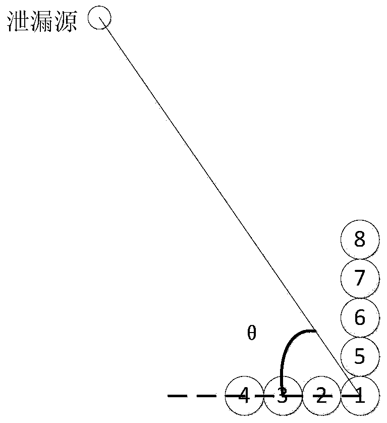
[0033] figure 1 It is a schematic diagram of leak orientation using an 8-element L-shaped acoustic emission sensor array in the present invention. The present invention uses 8 array element L type acoustic emission sensor arrays, 8 40dB preamplifiers (purchased from PAC company) and 8 channel signal acquisition analyzers, 8 array element sensor arrays are fixed on the inner surface of the spacecraft cabin by coupling agent, The sensor array is in electrical communication with the preamplifier and the signal acquisition analyzer. The method uses an 8-element L-shaped acoustic emission sensor ...


PUM


Abstract

The invention discloses a spacecraft ontrack leakage orientation method. According to the method, an 8-array-element L-shaped acoustic emission sensor array, 8 preamplifies and an 8-channel signal collecting and analyzing instrument are adopted, the sensor array is fixed to the inner surface of a spacecraft cabin through coupling agents and electrically communicates with the preamplifies and the 8-channel signal collecting and analyzing instrument. Leakage test is conducted within the range of a circle with the radius being equal to 2 meters through the L-shaped acoustic emission sensor array, when leakage occurs, acoustic emission signals generated by friction between the leaked gas and hole walls of leakage holes are propagated along the device wall continuously, all array elements collect the leaked acoustic emission signals synchronously, amplifying and filtering processing is conducted on the leaked acoustic emission signals, the signals are transmitted to the signal collecting and analyzing instrument, whether leakage occurs or not is judged by detecting changes of energy of the leaked acoustic emission signals, and when it is determined that leakage occurs, beam scanning is conducted on the leakage holes, and the directions of the leakage holes are determined.

Description

technical field [0001] The invention relates to a spacecraft on-orbit leak detection and leak hole orientation method, and belongs to the technical field of spacecraft on-orbit leak detection. Background technique [0002] With the increasing frequency of human spaceflight activities, the number of space debris has increased sharply, and the probability of leakage caused by the impact of space debris on orbiting spacecraft has increased significantly. The normal operation of the spacecraft, the life, work and life safety of the astronauts all require the spacecraft to provide a stable atmospheric environment, which puts forward high reliability sealing requirements for each sealed compartment. [0003] At present, some research work has been done on leak detection and orientation technology of on-orbit spacecraft at home and abroad. The research methods mainly include optical method, pressure change method, resistance change method, gas ionization method, ultrasonic method, ...

Claims


Application Information

Patent Timeline
Patent Type & Authority Applications(China)
IPC IPC(8): G01M3/24
Inventor 綦磊孟冬辉孙立臣闫荣鑫王勇孙伟郎冠卿李晓阳窦威任国华李唯丹
Owner BEIJING INST OF SPACECRAFT ENVIRONMENT ENG
Why Eureka
Try Eureka