Welding method for steel plate of ocean platform

A welding method and offshore platform technology, applied to welding equipment, welding accessories, welding/welding/cutting items, etc., to achieve significant progress, highlight substantive features, and avoid arcing effects

Inactive Publication Date: 2015-03-04
SHANDONG IRON & STEEL CO LTD
View PDF7 Cites 22 Cited by
  • Summary
  • Abstract
  • Description
  • Claims
  • Application Information

AI Technical Summary

Problems solved by technology

Meet the CTOD test requirements o

Method used


Image

  • Welding method for steel plate of ocean platform
  • Welding method for steel plate of ocean platform

Examples


specific Embodiment approach 1

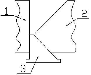
[0027] As can be seen from the accompanying drawings, a steel plate welding method for an offshore platform of the present scheme is characterized in that it comprises the following steps:

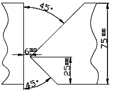
[0028] 1) The thickness of the steel plate used is 75mm, and the groove is processed on the steel plate joint, and the groove is assembled to make the groove K-shaped. The steel plate is processed by mechanical milling to form the groove. The depth of the upper part of the groove is 50mm, and the depth of the lower part of the groove is 25mm, that is, the ratio of the depth of the front side of the groove to the depth of the back side is 2:1, the angle of the groove is 45°, the root of the K-shaped groove is a gap of 6mm, and the size of the blunt side of the groove is 0mm;

[0029] 2) Fix the water-cooled copper strip on the back of the K-shaped groove, and the water-cooled copper strip is used to lift the molten pool during the front bottom welding;

[0030] 3) First, preheat the steel p...

specific Embodiment 2

[0034] As can be seen from the accompanying drawings, a steel plate welding method for an offshore platform of the present scheme is characterized in that it comprises the following steps:

[0035] 1) The thickness of the steel plate used is 75mm, and the groove is processed on the steel plate joint, and the groove is assembled to make the groove K-shaped. The steel plate is processed by mechanical milling to form the groove. The depth of the upper part of the groove is 50mm, and the depth of the lower part of the groove is 25mm, that is, the ratio of the depth of the front side of the groove to the depth of the back side is 2:1, the angle of the groove is 45°, the root of the K-shaped groove is a gap of 6mm, and the size of the blunt side of the groove is 0mm;

[0036] 2) Fix the water-cooled copper strip on the back of the K-shaped groove, and the water-cooled copper strip is used to lift the molten pool during the front bottom welding;

[0037] 3) First, preheat the steel p...


PUM

PropertyMeasurementUnit
Sizeaaaaaaaaaa
Diameteraaaaaaaaaa

Abstract

The invention provides a technical scheme for a welding method for a steel plate of an ocean platform. The welding method comprises the following steps: 1) processing an edge; 2) assembling the edge into a K-shaped edge and fixing a water-cooling copper strip on the rear side of the edge, wherein the water-cooling copper strip is used for lifting a molten pool during a front backing weld process; 3) during the front backing weld process, preventing the water-cooling copper strip from upward arcing at a welding moment; 4) performing rear backing weld; 5) performing filling welding: alternately performing front and rear filling welding by using flux cored wire gas shielded welding or submerged-arc welding according to the condition of angular deformation of a welded steel plate; 6) performing cosmetic welding: using the flux cored wire gas shielded welding or the submerged-arc welding. The K-shaped edge in asymmetrical depths is adopted; the water-cooling copper strip is used for lifting the molten pool during the front backing weld process; a distance from a welding wire to a straight edge side of the edge is strictly controlled by the filling welding; the lower welding heat input is adopted for the cosmetic welding, and a welding joint with the welding joint forming meeting the CTOD (crack tip opening displacement) test demand on the welding joint of the steel plate of the ocean platform is lastly acquired.

Description

technical field [0001] The invention relates to a welding method, in particular to a welding method that satisfies the crack tip opening displacement test (CTOD) of welded joints of thick steel plates for offshore platforms. Background technique [0002] The CTOD test of welded joints is an important experimental method for evaluating the toughness of welded joints of thick steel plates for offshore platforms. Offshore platforms are subjected to shock loads such as storms, tides, and even earthquakes during their service, which requires the welded joints of the platform to have the necessary toughness to avoid the danger of brittle fracture. With the development of offshore oil production in the deep sea, the thickness of the steel plate of the oil production platform structure is increasing, and the thicker the steel plate, the more difficult it is to guarantee the toughness of the steel plate. In addition, in order to improve the welding efficiency, the welding of thick p...

Claims


Application Information

Patent Timeline
IPC IPC(8): B23K9/16B23K9/18B23K101/18
CPCB23K9/16B23K9/18B23K9/32B23K33/00B23K2101/185
Inventor 李敏刘晓东朱延山徐洪庆李旺生王勇王焕洋李建磊王南辉
Owner SHANDONG IRON & STEEL CO LTD
Why Eureka
Try Eureka