Al technical title is built by PatSnap Al team. It summarizes the technical point description of the patent document.
A hydraulic power station, multi-functional technology, applied in the direction of fluid pressure actuation device, fluid pressure actuation system components, energy industry, etc., can solve the problems of high hydraulic oil temperature, waste of electric energy, long unimpeded circulation time of hydraulic oil, etc.
Active Publication Date: 2016-09-07
范清云 +1
View PDF7 Cites 0 Cited by
Summary
Abstract
Description
Claims
Application Information
AI Technical Summary
This helps you quickly interpret patents by identifying the three key elements:
Problems solved by technology
Method used
Benefits of technology
Problems solved by technology
Even so, it is still unavoidable that the load torque is too large or too small, and it is difficult to ensure the quality of the load—that is, the torque is too large or too small when the drill pipe or casing is unloaded, resulting in a product failure rate High, or even damage—that is, the phenomenon of twisting the string thread due to excessive torque; because the electric control box is controlled by the start-stop button, there are more than 60% of the gap time in the working process (the pump unit is still in the intermittent period) No-load operating conditions), so that the pump unit is always in a non-stop running state, especially in summer, the hydraulic oil temperature is high, not only the waste of electric energy is serious, but also because the hydraulic oil circulates for a long time, the hydraulic oil heats up quickly, poor security
Method used
Image
Click on the blue label to locate the original text in one second.
Reading with bidirectional positioning of images and text.
Examples
Embodiment
[0062] Embodiment A new type of hydraulic power station
[0063] Present embodiment completes by the design of two accompanying drawings:
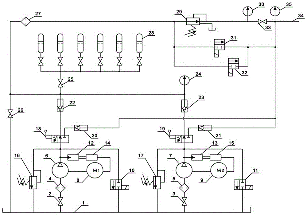
[0064] figure 1 Shows the structure and hydraulic working principle of the hydraulic power station of this embodiment
[0065] Such as figure 1 Shown: 1 is oil tank, 2 and 3 are low-pressure ball valves, 4 and 5 are low-pressure filters, 6 and 7 are plunger pumps, 8 is motor M1 (explosion-proof), 9 is motor M2 (explosion-proof), 10, 11 It is a normally open solenoid valve, 12 and 13 are electronic pressure transmitters, 14 and 15 are explosion-proof electric control boxes, 16 and 17 are overflow valves, 18 and 19 are manual reversing valves, 20, 21, 22, and 23 are One-way valve, 25, 26 and 33 are cut-off valves, 27 is a high-pressure filter, 28 is an accumulator, 29 is a manual pressure-reducing and pressure-regulating overflow valve, 31, 32 are normally closed solenoid valves, 24, 30 And 35 are pressure gauges, and 34 are high-pressur...
PUM
Abstract
The invention relates to a multifunctional hydraulic power station, which mainly consists of two pump groups, an electric cabinet, a hand-operated direction valve, a check valve, an overflow valve, an energy accumulator, a manual pressure-reduction pressure-regulation overflow valve, a normally-closed solenoid valve, a normally-opened solenoid valve, a stop valve, a high-pressure oil output end and an automatic control device. On the basis that the hydraulic power station has an original function, the defects and the deficiencies of an original hydraulic power station are overcome, and functions, such as free regulation of oil pressure, optimal torque control, energy saving and accumulation, multifunctional changeover, no-load time delay startup and automatic control, which are provided for a load, are increased. The multifunctional hydraulic power station is simple in operating, saves electric energy by more than 50%, can provide hydraulic power for various petroleum drilling tools, is also suitable for other industries to provide hydraulic power for hydraulic tools by taking high-pressure hydraulic oil as mediums, and can achieve the effects of energy saving, energy accumulation and controllable torque.
Description
technical field [0001] The invention relates to oil and gas extraction machinery for oil drilling, in particular to a device providing hydraulic power for oil drilling tools. Background technique [0002] The main function of the hydraulic power station is to provide hydraulic power for oil drilling tools (such as drill pipe power tongs and casing power tongs). A drilling tool is a device that provides string threading for drilling pipe or casing. [0003] The traditional hydraulic power station has a fuel tank-mounted structure as a whole. It is mainly composed of a fuel tank, a pump unit and an electric control box for the pump unit. The pump unit is placed under the fuel tank. The pump unit of this machine is composed of a low-pressure ball valve, a filter, a plunger pump, and a motor connected front and rear, and the motor provides driving power for the plunger pump. Under the control of the start and stop buttons of the electric control box, the pump unit outputs the ...
Claims
Application Information
Patent Timeline
Application Date:The date an application was filed.
Publication Date:The date a patent or application was officially published.
First Publication Date:The earliest publication date of a patent with the same application number.
Issue Date:Publication date of the patent grant document.
PCT Entry Date:The Entry date of PCT National Phase.
Estimated Expiry Date:The statutory expiry date of a patent right according to the Patent Law, and it is the longest term of protection that the patent right can achieve without the termination of the patent right due to other reasons(Term extension factor has been taken into account ).
Invalid Date:Actual expiry date is based on effective date or publication date of legal transaction data of invalid patent.