Trolley for receiving and dispatching oil and gas pipeline detection equipment
A technology for oil and natural gas and pipeline detection, applied in mechanical equipment, pipe components, pipes/pipe joints/pipe fittings, etc., can solve the problems of oil and natural gas leakage, unsafe transmission and reception of detection equipment, etc., and achieves strong applicability, simple structure, The effect of convenient transportation
- Summary
- Abstract
- Description
- Claims
- Application Information
AI Technical Summary
Problems solved by technology
Method used
Image

Examples
Embodiment Construction
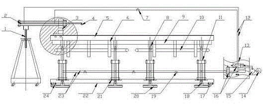
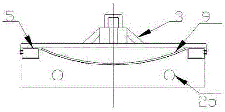
[0016] see figure 1 , 2 , which are structural schematic diagrams of an oil and gas pipeline detection transceiver equipment trolley according to the present invention. As shown in the figure: it is assembled by a carrying device, a booster device, a power system and a moving device.
[0017] Its specific structure is as follows:
[0018] The bearing device includes an arc bearing plate 9, 4-10 bottom reinforcing ribs 6, 2-4 bearing beams 5, 4-8 supporting hydraulic cylinders 11, 2-4 base beams 22 and 4-8 The base bearing platform 20; wherein: the arc bearing plate 9 and the bottom reinforcement rib 6 are connected together by welding, the bottom reinforcement rib 6 and the load beam 5 are welded together, and the load beam 5 is connected to the supporting hydraulic cylinder 11 through the first pin 8 Together, the supporting hydraulic cylinder 11 and the base beam 22 are connected together by the first screw 21 , and the supporting hydraulic cylinder 11 and the base bearin...
PUM
 Abstract
Description
Claims
Application Information
PatSnap Eureka turns technology decisions into work you can execute. Powered by our Innovation Knowledge Graph, it runs expert workflows across engineering, life sciences, materials and intellectual property. Get your review-ready output in minutes.


