Solar Auxiliary Power Negative Pressure Biomass Gasifier
What is Al technical title?
Al technical title is built by PatSnap Al team. It summarizes the technical point description of the patent document.
A technology for auxiliary power and gasification furnace, which is applied in the direction of electrical components, energy input, household stove/stove, etc. It can solve the problems of difficult life energy consumption, gas leakage, and large volume, so as to avoid gas leakage and increase fuel consumption. The effect of low utilization rate and investment cost
Inactive Publication Date: 2016-08-31
UNIV OF SCI & TECH LIAONING
View PDF15 Cites 0 Cited by
Summary
Abstract
Description
Claims
Application Information
AI Technical Summary
This helps you quickly interpret patents by identifying the three key elements:
Problems solved by technology
Method used
Benefits of technology
Problems solved by technology
However, because the above-mentioned systems and devices are too bulky, and the biomass gasifier is mostly used as an auxiliary heat source to assist solar power generation, it is difficult to solve the problem of energy consumption in remote areas and outdoors
[0009] If it is possible to design a negative pressure biomass gasifier that maintains all the structures and functions of the gasifier when it is connected, and disassembles and refills it separately when it is idle, it will definitely solve the problem of being difficult to carry and easy to gas when used in remote areas and outdoors. Disadvantages such as leakage and easy fire
Method used
Image
Click on the blue label to locate the original text in one second.
Reading with bidirectional positioning of images and text.
Examples
Embodiment Construction
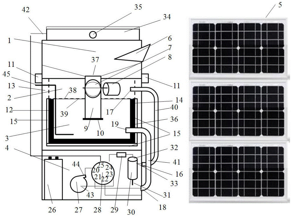
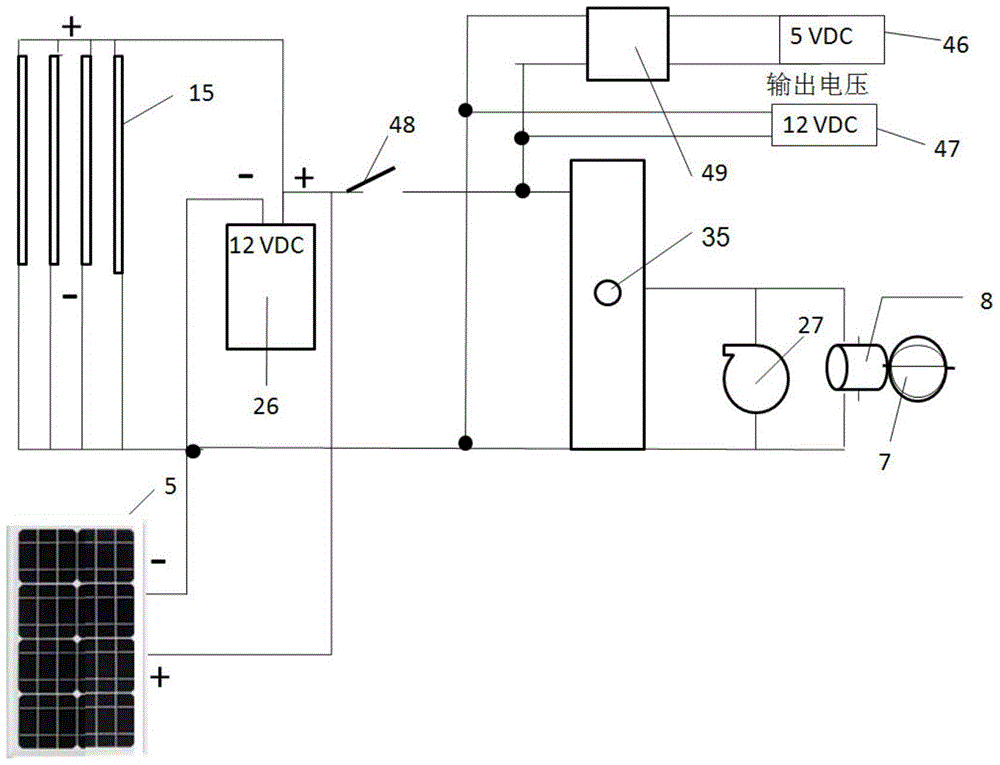
[0031] like figure 1 and figure 2 As shown, a solar-assisted power type negative pressure biomass gasifier consists of a biomass bin 1, a drying chamber 2, a combustion chamber 3, a control box 4, a photovoltaic panel 5, a feed blade 7, a stepping motor 8, a solid Feed connecting pipe 9, positive pressure isolation plate 10, buckle 11, combustion chamber liner 12, combustion chamber insulation layer jacket 13, thermoelectric power generation sheet 15, lead battery 26, centrifugal fan 27, six-way valve 28, dust removal and purification pipe 29. Tar separation tank 30, stove 34, phase change heat storage material injection port 36, sieve plate 38, drying chamber connecting pipe 40, combustion chamber connecting pipe 41, ignition device 45, 5.5VDC power output port 46 and 12VDC power output Port 47 is composed. The biomass material bin 1 is located at the upper section of the gasifier, and has a biomass bin door 6 that can be opened and closed on its side, and a single hob sto...
PUM
Abstract
The invention discloses a solar-assisted power negative pressure biomass gasifier, which is applied to remote areas and outdoors. The gasifier includes: biomass silo, drying chamber, combustion chamber, control box, photovoltaic panel, feeding blade and stepping motor, solid feeding connection pipe, positive pressure isolation plate, snap, combustion chamber liner, Insulation layer jacket of combustion chamber, thermoelectric power generation sheet, lead battery, centrifugal fan, six-way valve, dust removal and purification pipe, tar separation tank, stove, phase change heat storage material injection port, sieve plate, drying chamber connection pipe, combustion chamber connection tube, ignition device, 5.5VDC power outlet and 12VDC power outlet. The invention can still provide living energy, charge mobile phones and electronic products under extreme conditions, and ensure the normal life and external communication of users. The gasifier has a stable structure, easy installation and operation, and a wide range of applications.
Description
technical field [0001] The invention relates to a gasification furnace, in particular to a solar-assisted power type negative pressure biomass gasification furnace Background technique [0002] Biomass gasifier, as a biomass energy conversion equipment, can be used to solve all-day living energy. Available biomass resources include: crop straw, forest waste, edible fungus residue, cattle and sheep manure and all combustible substances. Although biomass raw materials are freely available in rural courtyards, fields and outdoors, most biomass gasifiers are still limited to households, restaurants, kitchens, markets, power plants and other places. This is because the biomass gasifier usually needs to power the fan to ensure that the combustible gas components produced are taken out and utilized in time. [0003] For some remote areas or outdoor areas without electricity and fuel supply, living energy is greatly limited. When food processing is carried out, firewood, stoves, g...
Claims
Application Information
Patent Timeline
Application Date:The date an application was filed.
Publication Date:The date a patent or application was officially published.
First Publication Date:The earliest publication date of a patent with the same application number.
Issue Date:Publication date of the patent grant document.
PCT Entry Date:The Entry date of PCT National Phase.
Estimated Expiry Date:The statutory expiry date of a patent right according to the Patent Law, and it is the longest term of protection that the patent right can achieve without the termination of the patent right due to other reasons(Term extension factor has been taken into account ).
Invalid Date:Actual expiry date is based on effective date or publication date of legal transaction data of invalid patent.