
X-ray diffractometer in situ battery accessory, heating device, cooling device and measuring method

An X-ray and diffractometer technology, applied in the field of battery measurement, can solve the problems of many assembly parts, complex design, and high price, and achieve good air tightness, ensure electrical conductivity, and simple design

Active Publication Date: 2015-03-04
苏州亿凡星仪器科技有限公司
View PDF7 Cites 19 Cited by
  • Summary
  • Abstract
  • Description
  • Claims
  • Application Information

AI Technical Summary

Problems solved by technology

However, the existing patented technology has disadvantages such as high price (such as Japanese science), complicated operation, etc.
For example, although a foreign patent (US5635138) can realize the test function of in-situ battery XRD, it has too many assembly parts, complex design, and difficult application, which is not suitable for the configuration of mainstream domestic diffractometers.
[0003] Although some other domestic patents (such as CN100373168C, CN102435625A, CN203434214U) can also perform in-situ battery measurement of XRD, a common feature is that the compactness of the measurement electrode part is not good, or that the battery material and the electrode of the collector are poor. The contact is not good enough, which affects the conductivity, and then affects the phase transition process of the battery material, and cannot really realize the research significance of in-situ battery accessories

Method used


Image

  • X-ray diffractometer in situ battery accessory, heating device, cooling device and measuring method
  • X-ray diffractometer in situ battery accessory, heating device, cooling device and measuring method
  • X-ray diffractometer in situ battery accessory, heating device, cooling device and measuring method

Examples


Embodiment 1

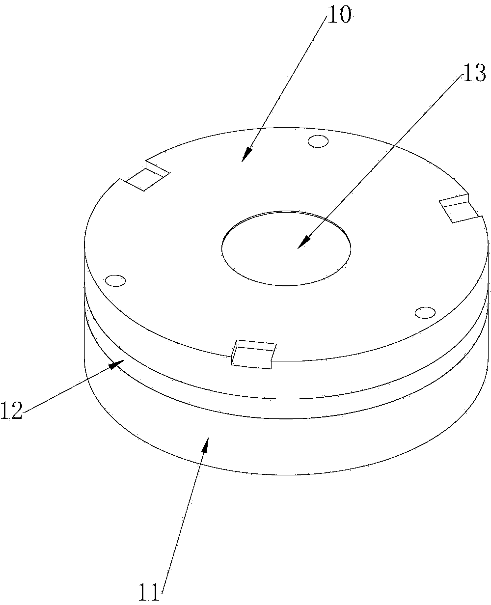
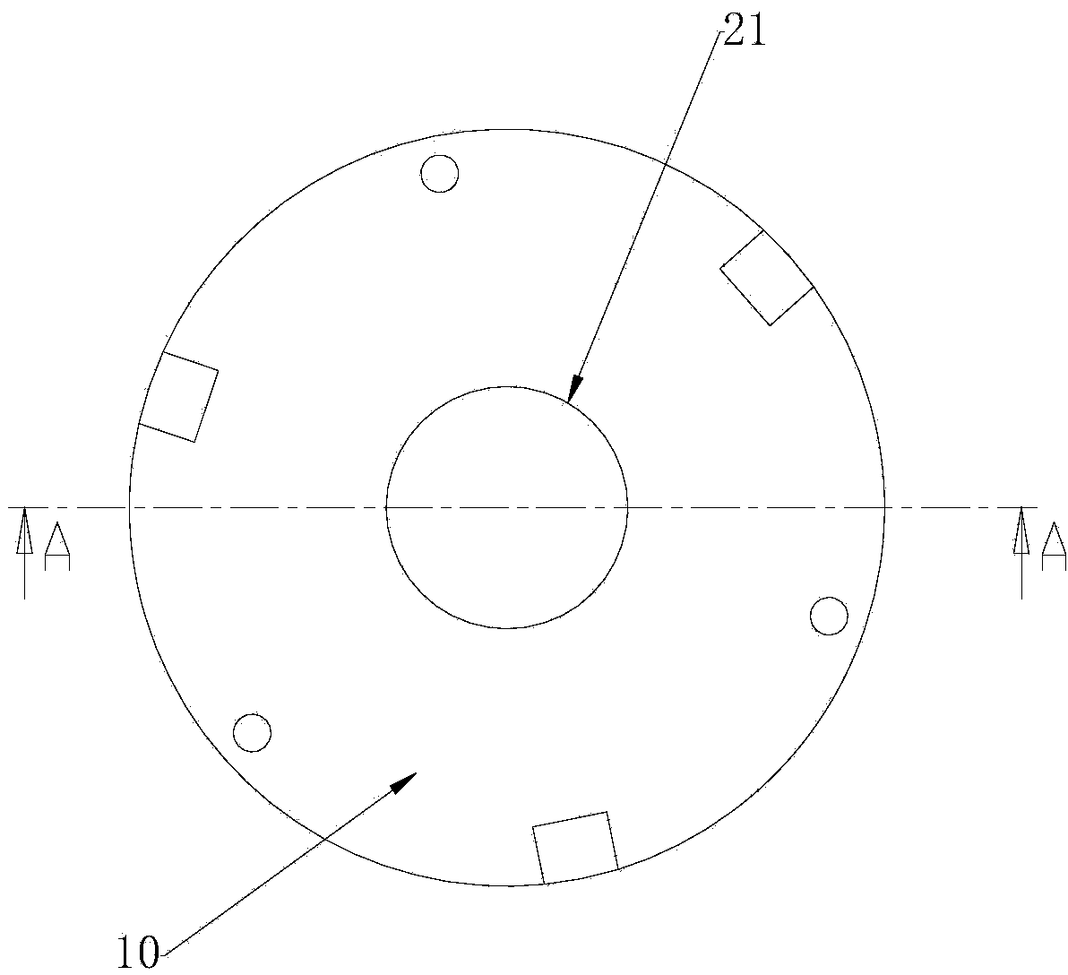
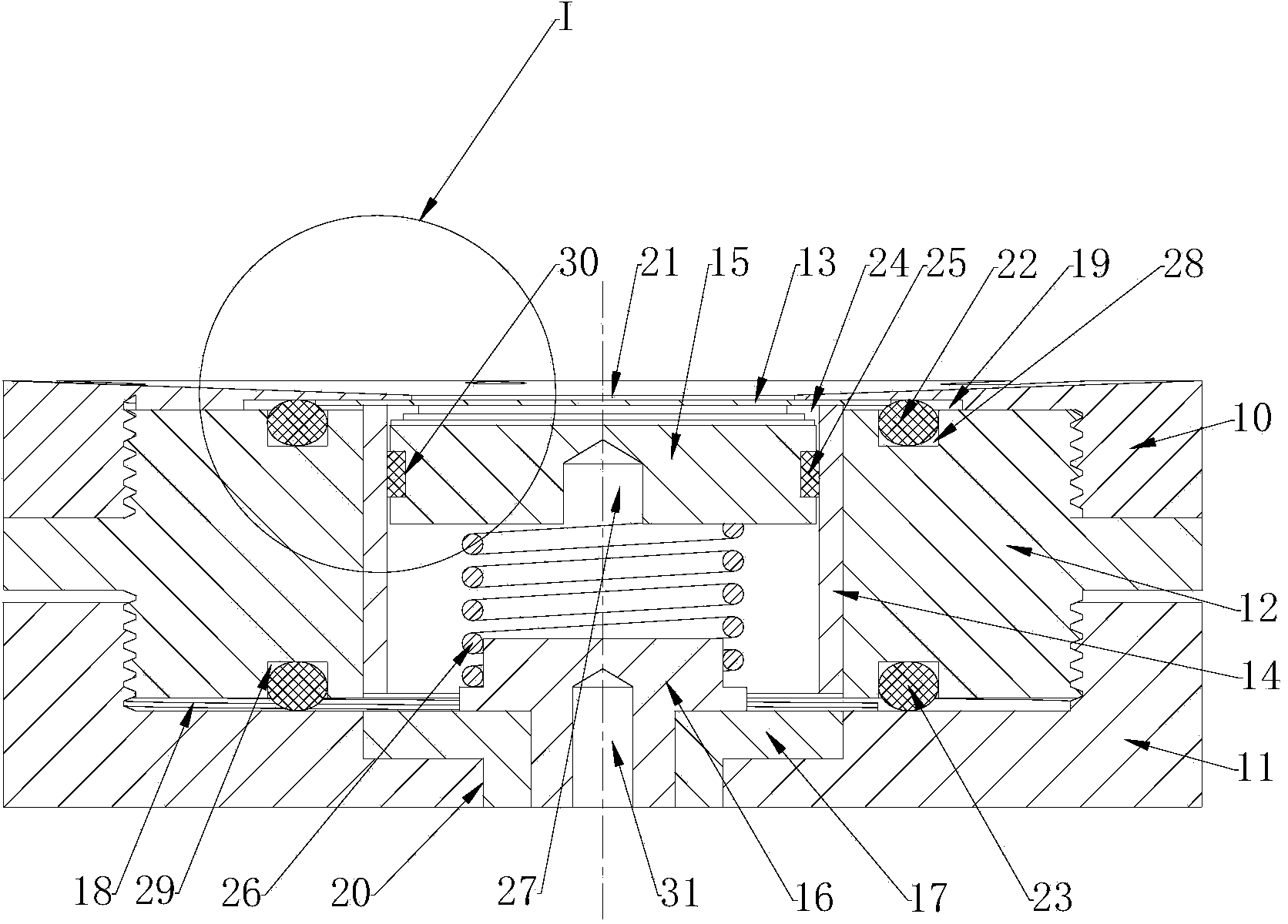
[0044] This embodiment provides an in-situ battery accessory for an X-ray diffractometer, such as Figure 1-4 As shown, it includes an upper top cover 10 , a lower top cover 11 , a central bolt 12 , a beryllium window 13 , a central cavity insulator 14 , a negative conductive seal 15 , a central electrode 16 and a central insulator 17 .

[0045] to combine Figure 5 As shown, the upper end surface of the lower top cover 11 is provided with a first threaded hole 18, and the lower end surface of the upper top cover 10 is provided with a second threaded hole 19, the first threaded hole 18 and the second threaded hole 19 are blind holes , the upper end of the central bolt 12 is installed in the second threaded hole 19 , and the lower end of the central bolt 12 is installed in the first threaded hole 18 . The upper top cover 10, the lower top cover 11 and the central bolt 12 are all made of conductive materials, such as stainless steel.

[0046] A first sealing ring 22 is provide...

Embodiment 2

[0056] This embodiment provides a heating device for an in-situ battery accessory of an X-ray diffractometer, such as Figure 8 As shown, it includes a first housing 50 and a first upper cover 51 . Both the first casing 50 and the first upper cover 51 are made of steel. The first casing 50 is in a tubular shape with the lower end closing the upper opening. The first upper cover 51 is fixedly installed on the first casing 50 , and the first upper cover 51 closes the upper opening of the first casing 50 . A sealing ring can be installed between the first upper cover 51 and the first housing 50 . A first window 52 and a second window 53 are opened on the side wall of the first housing 50 , the first window 52 is opposite to the second window 53 , and both the first window 52 and the second window 53 are rectangular holes. Both the first window 52 and the second window 53 are sealed by polyimide tape.

[0057] A heater and a temperature sensor are fixedly installed in the first...

Embodiment 3

[0060] Such as Figure 6 As shown, this embodiment provides a cooling device for an in-situ battery accessory of an X-ray diffractometer, including a second casing 70 and a second upper cover 71 . The second housing 70 and the second upper cover 71 are made of polytetrafluoroethylene or similar materials with low thermal conductivity (such as plexiglass, polypropylene, polyethylene, polystyrene, etc.). The second housing 70 is in the shape of a tube with the lower end closing the upper opening. The second upper cover 71 is fixedly mounted on the second housing 70. The second upper cover 71 closes the upper opening of the second housing 70. Between the second upper cover 71 and A sealing ring may be installed between the second shells 70 . The side wall of the second housing 70 is provided with a third window 72 and a fourth window 73, the third window 72 and the fourth window 73 are oppositely arranged, the third window 72 and the fourth window 73 are rectangular holes, the t...


PUM


Abstract

The invention discloses an X-ray diffractometer in situ battery accessory which comprises an upper top cover, a lower top cover, a center bolt, a beryllium window, a center cavity insulating part, a cathode conductive sealing part, a center electrode and a center insulator, wherein the upper end of the center bolt is mounted in a second threaded hole; the beryllium window is mounted at the bottom of the second threaded hole; the beryllium window seals the second threaded hole; the center cavity insulating part is mounted in a through hole of the center bolt; the upper end of the center cavity insulating part is in contact with the beryllium window; the cathode conductive sealing part is mounted in the inner chamber of the center cavity insulating part; the center insulator is fixedly mounted in a first through hole; the center electrode is fixedly mounted in a through hole of the center insulator; the upper end of the center electrode is connected with the cathode conductive sealing part. The device is simple in design, convenient to use, and good in air sealing property. The invention also discloses a heating device and a cooling device for the X-ray diffractometer in situ battery accessory as well as a method for measuring a lithium battery material by using the X-ray diffractometer in situ battery accessory.

Description

technical field [0001] The invention relates to the field of battery measurement, in particular to an X-ray diffractometer in-situ battery accessory, a heating device, a cooling device thereof, and a method for measuring lithium battery materials using the X-ray diffractometer in-situ battery accessory. Background technique [0002] Lithium battery material is one of the very important battery raw materials at present. The development of lithium battery material is a very important research direction in recent years. X-ray diffraction is an indispensable and important means for lithium battery material research. In situ battery attachments that can perform X-ray diffraction have been the focus of this technology. Using the XRD (X-ray diffraction) in-situ battery accessory, the phase and structure of the battery material during the charge-discharge cycle can be observed in real time, avoiding the deviation of the experimental results caused by static and quasi-static measurem...

Claims


Application Information

Patent Timeline
IPC IPC(8): H01M2/20H01M2/10H01M2/04H01M2/08G01N23/20H01M50/147H01M50/166H01M50/188H01M50/503
CPCH01M10/48G01N23/20091H01M50/166H01M50/147H01M50/256H01M50/183H01M50/50Y02E60/10
Inventor 侯燕
Owner 苏州亿凡星仪器科技有限公司
Learn More