Linear oscillation motor
An oscillating motor and linear technology, applied in the electromagnetic field, can solve problems such as hydraulic pump friction and leakage, complex redundancy configuration, and dynamic performance degradation, and achieve the effects of reducing magnetic flux leakage, reducing mass, and improving dynamic performance
- Summary
- Abstract
- Description
- Claims
- Application Information
AI Technical Summary
Problems solved by technology
Method used
Image

Examples
Embodiment 1
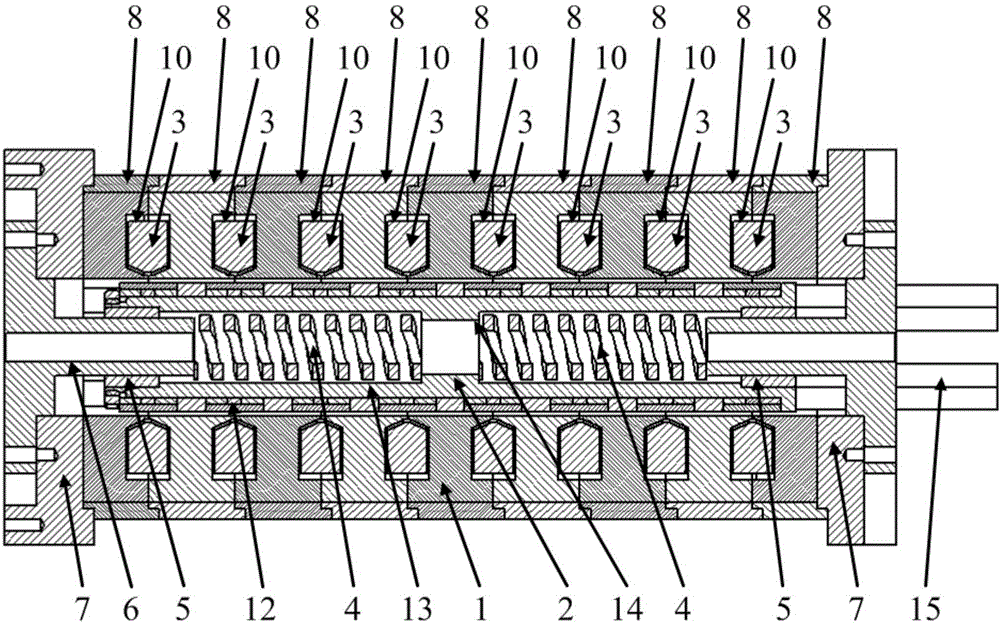
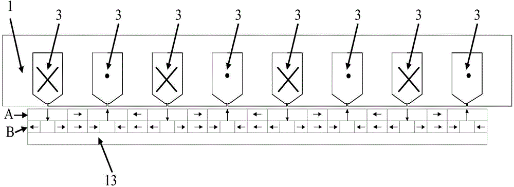
[0018] The present invention relates to a linear oscillating motor, see figure 1 , which includes an outer layer stator, an inner layer mover, and a hollow winding slot on the outer layer stator, wherein the outer layer stator is a hollow structure, and the inner layer mover is sleeved in the hollow structure, and the above-mentioned hollow winding slot is along the outer layer stator The extension direction of the axis is arranged. There are multiple hollow winding slots. Each hollow winding slot is an independent ring structure. They are formed around the axis of the outer stator. Each independent hollow winding slot has a A coil winding is wound. Of course, if the coil winding is formed by winding multiple turns of wire, the winding direction of the wire in at least one hollow winding slot is the same direction. The above-mentioned hollow winding slots provide space for the coil windings to be wound, and can fix or position the coil windings.
[0019] The above-mentioned ...
Embodiment approach
[0037] There may be six magnetic conductive blocks, and the six magnetic conductive blocks are arranged along the circumference and welded and fixed in the outer casing of the stator, and the winding slots on both sides of the magnetic conductive blocks are used to place the coil windings. For the convenience of understanding, such six magnetic conductive blocks are called magnetic conductive units. As shown in the figure, nine magnetic conductive units can be placed coaxially and compressed with interference fit to form the entire outer stator. Such nine magnetic conduction units can form eight hollow winding slots.
[0038] Of course, when the magnetic permeable block is a complete ring, several (complete) magnetic permeable blocks can also be coaxially placed and compressed with interference fit to form the entire outer layer stator. The stator outer casing can also be formed by splicing multiple pieces together.
[0039] In an optional embodiment, the linear oscillating m...
Embodiment 2
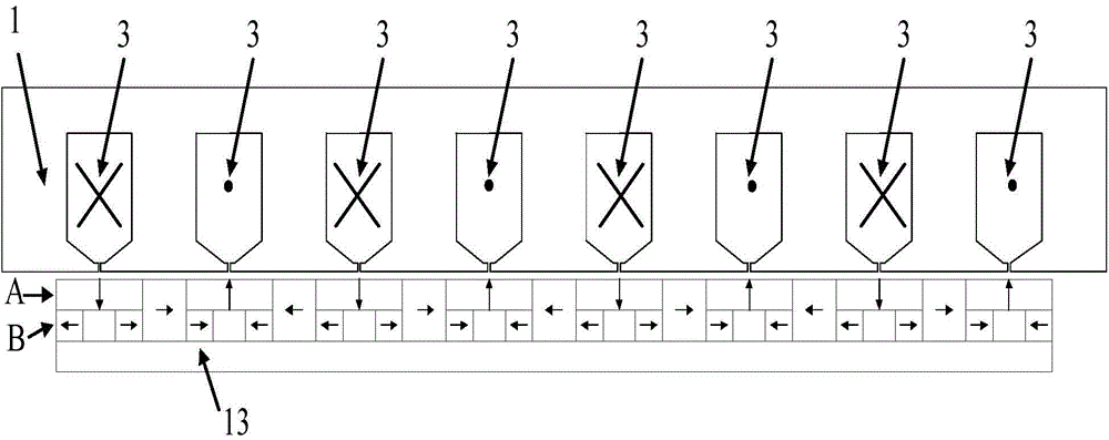
[0044] Compared with Example 1, the difference is that, in the way of setting the inner ring layer and the outer ring layer, the inner layer spacer magnet and the outer layer spacer magnet have an integrated structure, such as image 3 As shown, that is, they can be the same magnet. In this way, it is more convenient and quicker during manufacture. Other respects are all identical with embodiment 1.
PUM
 Abstract
Description
Claims
Application Information