Double-faced milling mechanism

A double-sided milling and milling machine technology, applied in the mechanical field, can solve the problems of reducing the stability of the milling machine mechanism, unable to realize adjustment in time, poor clamping effect, etc., to achieve convenient pattern layout, facilitate mass production, and improve space utilization. Effect

Inactive Publication Date: 2015-03-11
NINGBO HOYEA MACHINERY MFG
View PDF7 Cites 8 Cited by
  • Summary
  • Abstract
  • Description
  • Claims
  • Application Information

AI Technical Summary

Problems solved by technology

The structure design of existing milling machines is simple, and only one end face of a single valve body blank 10 is milled at a time. The valve body blank 10 can only mill the front face 14 and then the back face 15. In this way, the milling machine needs to retract the tool and process each face. Repeated operations of turning over, aligning, and feeding have low work efficiency, and the milling machine mechanism is generally equipped with blank clamps. Correspondingly, the blank clamps can only clamp a single valve body blank 10 at a time. 10 When the clamping position is shifted, the existing fixture cannot be adjusted in time, and the clamping effect is not good, which in turn reduces the stability of the milling machine mechanism and reduces the work efficiency

Method used


Image

  • Double-faced milling mechanism
  • Double-faced milling mechanism
  • Double-faced milling mechanism

Examples


Embodiment Construction

[0035]The following are specific embodiments of the present invention and in conjunction with the accompanying drawings, the technical solutions of the present invention are further described, but the present invention is not limited to these embodiments.

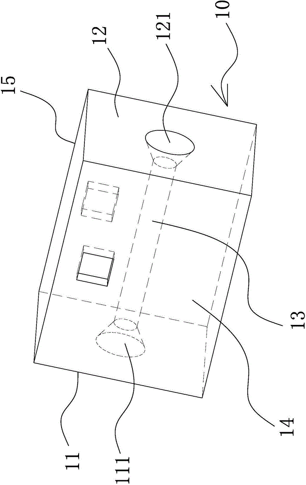
[0036] The existing milling machine mechanism for processing blanks such as solenoid valve bodies has a simple structural design, and only one end face of a single valve body blank 10 is milled at a time, and the corresponding blank clamp can only clamp a single valve body blank 10 at a time. The adjustment of the blank fixture is also inconvenient, and the clamping effect is not good, thereby reducing the stability and work efficiency of the milling machine mechanism. Therefore, it is necessary to design a more reasonable double-sided milling mechanism.

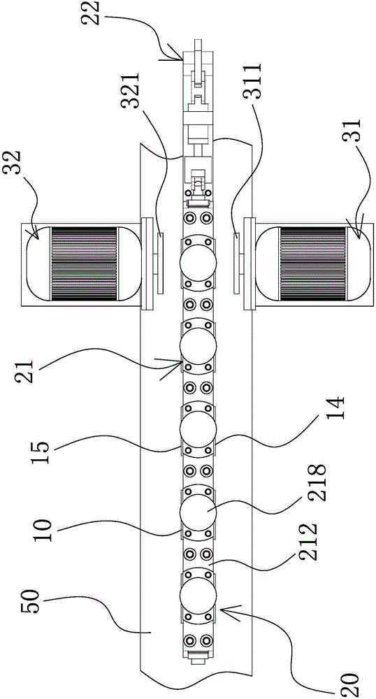
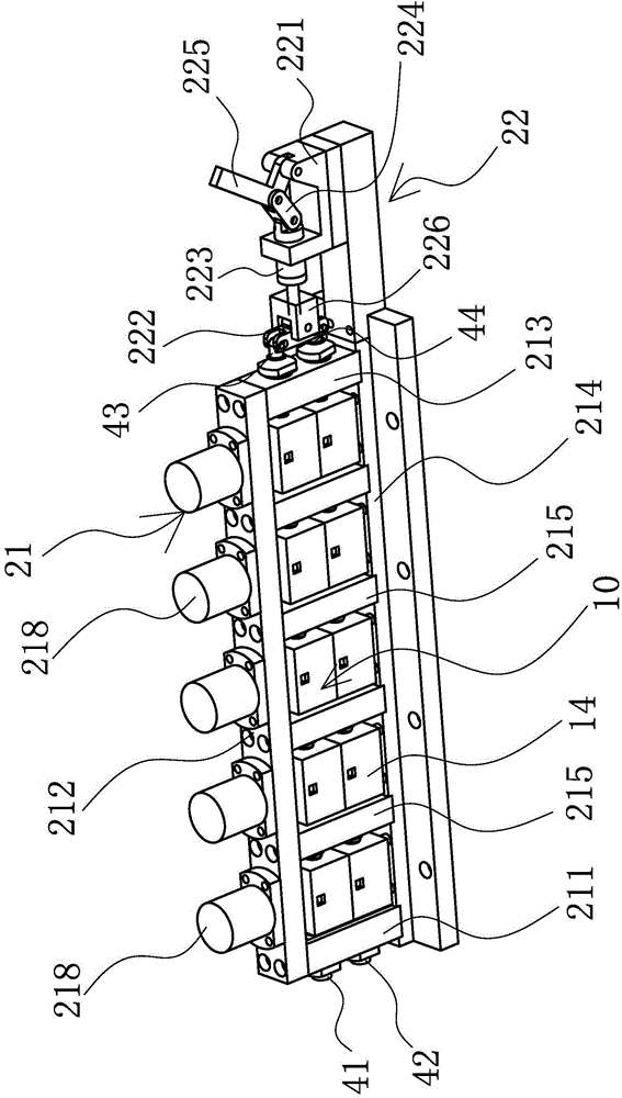
[0037] The invention protects a double-sided milling mechanism, which adopts double-sided milling to simultaneously mill the front 14 and the back 15 of blanks such as so...


PUM


Abstract

The invention provides a double-faced milling mechanism, which belongs to the machinery technical field. The double-faced milling mechanism comprises a milling machine clamp, a first milling machine and a second milling machine arranged at two sides of the milling machine clamp, the milling machine clamp comprises a clamp assembly used for clamping a valve blank and an adjusting assembly arranged outside the clamp assembly and used for clamping valve blanks, the clamp assembly comprises a left side plate, a cover plate, a right side plate, and a bottom plated which are capable of encircling a frame form structure, at least an intermediate baffle plate which is vertically arranged is provided between the left side plate and the right side plate, two ends of each intermediate baffle plate are respectively connected to the cover plate and the bottom plate, the left side plate, the cover plate, the right side plate, the bottom plate and the intermediate baffle plate are capable of encircling at least two clamp chambers used for placing the valve blank; a first milling cutter used for milling the right side of the valve blank is vertically arranged on the first milling machine, a second milling cutter used for milling the back side of the valve blank is vertically arranged on the second milling machine. The double-faced milling mechanism has the advantages of reasonable design, high work efficiency and wide versatility.

Description

technical field [0001] The invention belongs to the technical field of machinery, and relates to a double-sided milling mechanism, in particular to a double-sided milling mechanism suitable for processing blanks such as solenoid valve bodies. Background technique [0002] Solenoid valve is an industrial equipment controlled by electromagnetic. It is an automatic basic component used to control fluid. It belongs to actuator and is not limited to hydraulic and pneumatic. It is used in industrial control system to adjust the direction, flow, speed and other parameters of medium. . Solenoid valves can cooperate with different circuits to achieve the expected control, and the control accuracy and flexibility can be guaranteed. There are many kinds of solenoid valves. Different solenoid valves play a role in different positions of the control system. The most commonly used ones are check valves, safety valves, directional control valves, and speed regulating valves. [0003] The...

Claims


Application Information

Patent Timeline
Patent Type & Authority Applications(China)
IPC IPC(8): B23C3/05B23Q3/08
CPCB23C3/058B23Q3/082B23Q2703/04
Inventor 翁之旦郭际刚刘博陈飞飞
Owner NINGBO HOYEA MACHINERY MFG
Why Eureka
Try Eureka