Welding method and welding structure of accelerometer movement

A technology of accelerometer and welding method, which is applied in the direction of measuring acceleration, speed/acceleration/impact measurement, welding equipment, etc., which can solve the problems of uneven distribution of the circumference, increased welding stress, and increased number of welding repairs, etc., to improve welding The effect of quality, low-stress welds

Active Publication Date: 2015-03-11
航天科工惯性技术有限公司
View PDF19 Cites 5 Cited by
  • Summary
  • Abstract
  • Description
  • Claims
  • Application Information

AI Technical Summary

Problems solved by technology

Insufficient laser incident energy will result in incomplete welding of the abdominal belt, increasing the number of repair welding and increasing the welding stress
Through the stress detection of the vertical weld seam direction on the circumference of the core belt in the current process, the stress difference between the two relative points has reached hundreds of MPa, and the circumferential distribution is extremely uneven, which affects the welding quality

Method used


Image

  • Welding method and welding structure of accelerometer movement
  • Welding method and welding structure of accelerometer movement
  • Welding method and welding structure of accelerometer movement

Examples


Embodiment 1

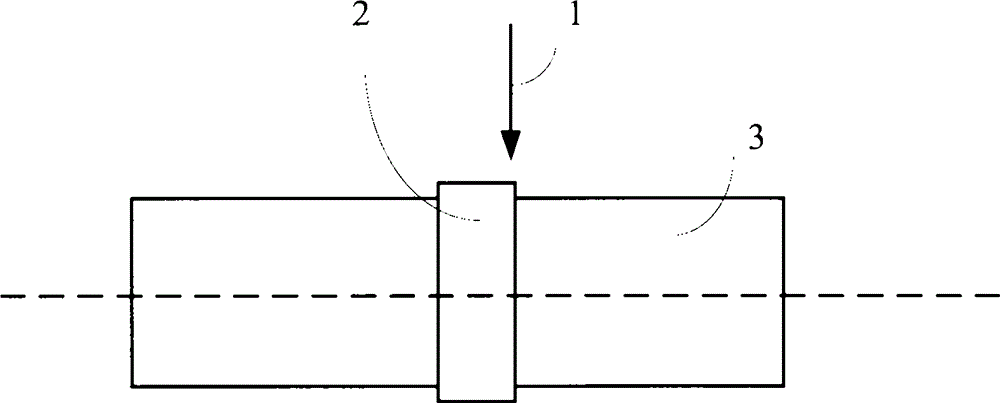
[0021] refer to figure 2 , the present embodiment provides a welding method for an accelerometer watch core, the watch core includes an upper torque device, a lower torque device and N sections of abdominal belt, and the method includes:

[0022] Step S101, binding N sections of abdominal belts to the junction of the upper torque device and the lower torque device, forming notches between each section of abdominal belt, wherein, 2≤N≤10;

[0023] Step S102, performing spot welding on each section of the abdominal belt, and pre-fixing the abdominal belt with the upper torque device and the lower torque device;

[0024] Step S103 , adjusting the position of the watch movement so that the central axis of the watch movement is at a preset angle with the laser beam, and continuously welding each section of the abdominal belt through the laser beam.

[0025] In the welding method and welding structure of the accelerometer watch core provided in this embodiment, the notch between th...

Embodiment 2

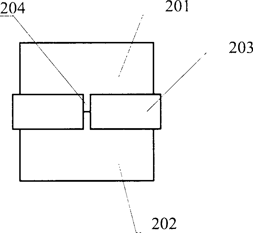
[0039] refer to image 3 , the present embodiment provides a welding structure of an accelerometer watch core, including an upper torque device 201, a lower torque device 202) and an N-section abdominal belt 203, and the N-section abdominal belt 203 is fixed on the upper torque device 201 and the lower torque device by welding At the joint of 202, notch 204 is formed between each section of abdominal belt 203, wherein, 2≤N≤10.

[0040] Wherein, the radians of the N sections of abdominal belt 203 can be the same or different, and can be set according to actual conditions.

[0041] As a preferred embodiment, refer to Figure 5 , Figure 5 The top view of an embodiment of the welded structure of the accelerometer watch core provided in this embodiment, the welded structure includes 7 sections of abdominal belt, and the 7 sections of abdominal belt are arranged symmetrically with respect to the longitudinal axis.

[0042] Such as Figure 5 As shown, the 7-section abdominal bel...


PUM


Abstract

The invention provides a welding method and welding structure of an accelerometer movement. The welding method comprises the steps that N belly bands are bundled at the combination position of an upper torquer and a lower torquer, and groove openings are formed between the belly bands, wherein N is larger than or equal to 2 and smaller than or equal to 10; spot welding is carried out on the belly bands, and the belly bands, the upper torquer and the lower torquer are fixed in advance; the position of the movement is adjusted to enable the central axis of the movement and a laser beam to form a preset angle, and the belly bands are continuously welded through the laser beam; and the groove openings of the N belly bands can effectively isolate welding stress to achieve low-stress welding, and in the continuous welding process, due to the fact that a certain preset angle is formed between the central axis of the movement and the laser beam, the edges of the belly belts are fully melted through energy of the laser beam, and the welding quality is improved.

Description

technical field [0001] The invention relates to the technical field of welding technology, in particular to a welding method and welding structure for an accelerometer watch core. Background technique [0002] The watch core of the quartz flexible accelerometer (hereinafter referred to as the accelerometer) is composed of an upper torque device, a pendulum assembly, a lower torque device and a belly band. When assembling the accelerometer watch core, the upper torque device, the lower torque device and the pendulum assembly are positioned by the V-shaped tooling, and the abdominal belt is put on the joint of the upper torque device, the lower torque device and the pendulum assembly, and then a certain pre-tightening force is applied. The three are clamped, and the upper torque device, the lower torque device and the abdominal belt are welded together by laser welding to realize the assembly of the watch movement. As the core component of the accelerometer, the assembly qual...

Claims


Application Information

Patent Timeline
Patent Type & Authority Applications(China)
IPC IPC(8): B23K26/70
CPCB23K26/20B23K26/22G01P15/00
Inventor 潘天鹏杨守安徐国栋刘洋杨杏敏李辉付秀娟张吉
Owner 航天科工惯性技术有限公司
Why Eureka
Try Eureka