Continuous vacuum ion plating machine

A technology of vacuum coating and coating machine, which is applied in ion implantation coating, vacuum evaporation coating, sputtering coating and other directions, can solve the problems of large volume, high production and manufacturing cost, and large space occupation, so as to reduce the manufacturing cost. , Small size, saving space

Inactive Publication Date: 2015-03-11
辽宁北宇真空科技有限公司
View PDF11 Cites 1 Cited by
  • Summary
  • Abstract
  • Description
  • Claims
  • Application Information

AI Technical Summary

Problems solved by technology

[0002] The traditional vacuum ion coating equipment is mainly composed of a discharge chamber, multiple coating chambers, multiple transition chambers and a receiving chamber. The whole set of coating equipment is bulky, and the length of the equipment is generally more than 18 meters. The equipment occupies a large space when installed. In addition, The above-mentioned vacuum ion coating equipment requires multiple sets of diffusion pump units, molecular pump units, mechanical pumps, and Roots pumps to carry out vacuuming operations, which not only consumes a lot of power, but also costs a lot to manufacture the whole set of equipment.

Method used


Image

  • Continuous vacuum ion plating machine
  • Continuous vacuum ion plating machine
  • Continuous vacuum ion plating machine

Examples


Embodiment Construction

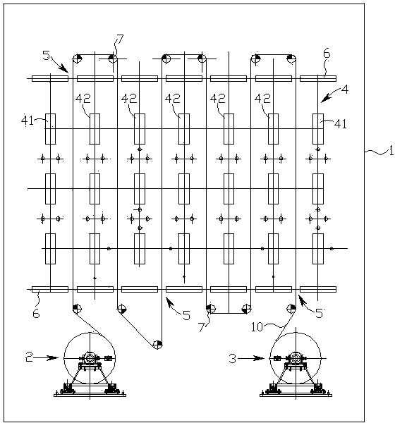
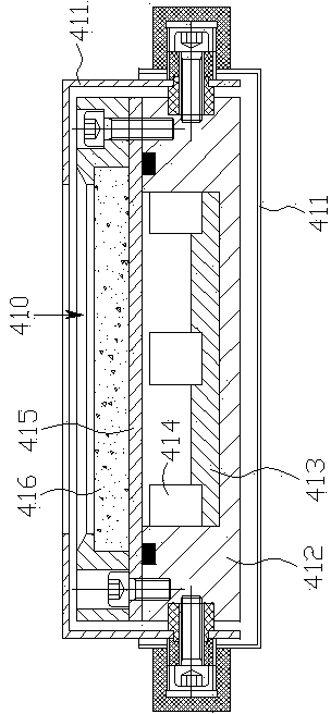
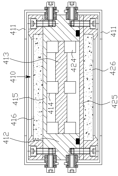
[0012] see figure 1 - image 3 , see first figure 1 , a continuous vacuum ion coating machine of the present invention has a box-type vacuum coating chamber 1, and the left and right sides of the box-type vacuum coating chamber are respectively provided with a base film unwinding mechanism 2 and a base film rewinding and deviation-correcting mechanism 3. There are multiple rows of planar magnetron sputtering targets 4 in the vacuum coating chamber from left to right, wherein the left and right rows are single-sided sputtering planar magnetron sputtering targets 41, and the ones between the left and right rows are double-sided sputtering targets. A planar magnetron sputtering target 42 is fired, and a coating channel 5 is formed between adjacent rows of planar magnetron sputtering targets 4. The front and rear sides of the multiple rows of planar magnetron sputtering targets 4 are respectively provided with water-cooled supporting plates. 6. A transmission roller 7 is provide...


PUM


Abstract

The invention discloses a continuous vacuum ion plating machine which is provided with a tank-type vacuum plating chamber, wherein the left and right sides in the tank-type vacuum plating chamber are respectively provided with a base film decoiling mechanism and a base film coiling centering mechanism; the inside of the tank-type vacuum plating chamber is provided with a plurality of rows of plane magnetron sputtering targets at intervals from left to right, the plane magnetron sputtering targets on the left and right rows are single-side-sputtering plane magnetron sputtering targets, and the plane magnetron sputtering targets between the left and right rows are double-side-sputtering plane magnetron sputtering targets; a plating channel is formed between every two adjacent rows of plane magnetron sputtering targets; the front and back sides of the plurality rows of plane magnetron sputtering targets are respectively provided with a water cooling backing plate; the outer side of each water cooling backing plate is provided with a driving roller which is positioned between every two adjacent rows of plane magnetron sputtering targets; and the base film arranged on the base decoiling mechanism passes through the plating channel via the driving rollers, and is centered by the base film coiling centering mechanism and then coiled. The continuous vacuum ion plating machine completes the decoiling, plating and coiling of the base film in one tank-type vacuum plating chamber, has the advantages of simple equipment structure and small size, and greatly lowers the manufacturing cost.

Description

technical field [0001] The invention relates to a continuous vacuum ion coating machine. Background technique [0002] The traditional vacuum ion coating equipment is mainly composed of a discharge chamber, multiple coating chambers, multiple transition chambers and a receiving chamber. The whole set of coating equipment is bulky, and the length of the equipment is generally more than 18 meters. The equipment occupies a large space when installed. In addition, The above-mentioned vacuum ion coating equipment requires multiple sets of diffusion pump units, molecular pump units, mechanical pumps, and Roots pumps to carry out vacuuming operations during operation, which not only consumes a lot of power, but also costs a lot to manufacture the whole set of equipment. Contents of the invention [0003] The technical problem to be solved by the present invention is to provide a continuous vacuum ion coating machine with simple structure, small footprint, low equipment manufactur...

Claims


Application Information

Patent Timeline
Patent Type & Authority Applications(China)
IPC IPC(8): C23C14/56C23C14/35
CPCC23C14/562
Inventor 关秉羽
Owner 辽宁北宇真空科技有限公司
Why Eureka
Try Eureka