
Groove testing rack for underwater inspection of diversion tunnel door gate groove of hydropower station and construction method

A technology for test tanks and hydropower stations, which is applied in hydropower stations, water conservancy projects, hydroelectric power generation, etc., and can solve the inspection restrictions and problems of inspection equipment and instruments that cannot be carried out, cannot be dismantled, and door slots and bottom sills are worn or scoured. impact and other issues, to achieve the effect of simple structure, simplified construction process, and strong resistance to water impact

Active Publication Date: 2015-03-11
HANGZHOU HUANENG SAFETY ENG POLYTRON TECH CO LTD
View PDF4 Cites 5 Cited by
  • Summary
  • Abstract
  • Description
  • Claims
  • Application Information

AI Technical Summary

Problems solved by technology

Since the water inlet gates of the diversion tunnel have been installed, they cannot be dismantled before the inspection, which has certain restrictions and influence on the inspection of the wear or erosion damage of the door slot and bottom sill
At the same time, general inspection equipment and instruments cannot be carried out under the state of high flow rate.

Method used


Image

  • Groove testing rack for underwater inspection of diversion tunnel door gate groove of hydropower station and construction method
  • Groove testing rack for underwater inspection of diversion tunnel door gate groove of hydropower station and construction method
  • Groove testing rack for underwater inspection of diversion tunnel door gate groove of hydropower station and construction method

Examples


Embodiment Construction

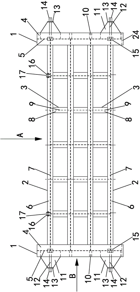
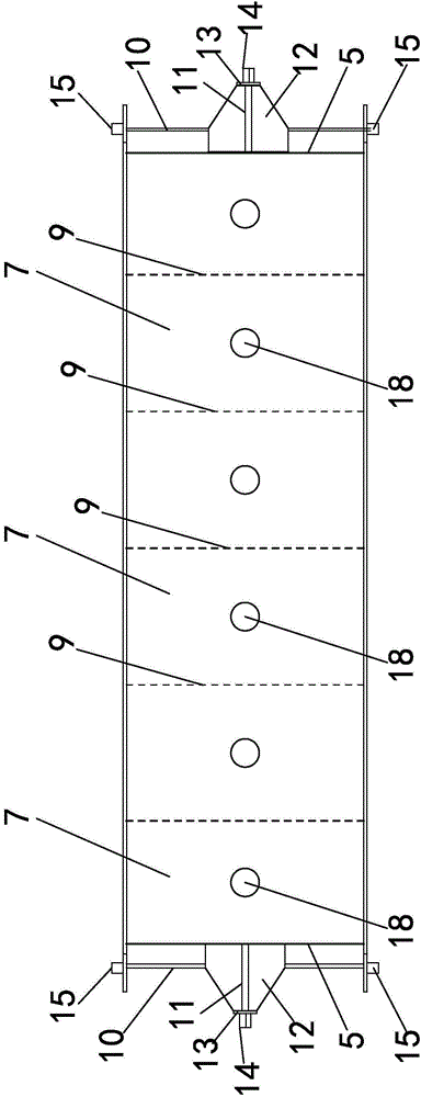
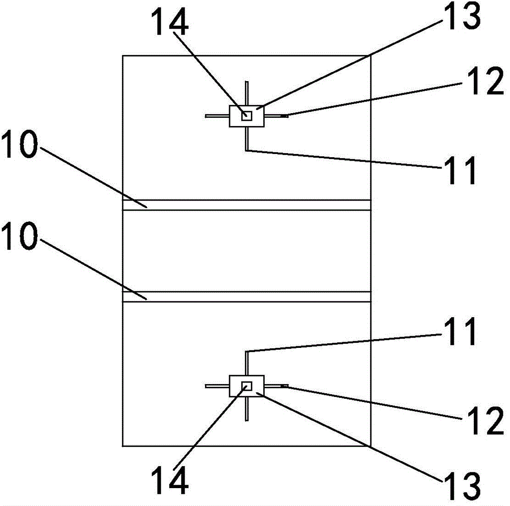
[0056] Such as Figure 1 to Figure 6 As shown, the test tank frame for underwater inspection of the diversion tunnel door slot of the hydropower station includes side column 1, main beam 2 and longitudinal beam 3, and side column 1, main beam 2 and longitudinal beam 3 are all steel structures. There are two side columns 1 on both sides, and the side columns 1 are vertically arranged and placed on the ground. Side column 1 includes side column web 5 and side column flange 4, each side column 1 includes two side column flanges 4, side column flange 4 is arranged on the outside of side column 1, side column flange 4 There are side column webs 5 connected between them. There are several main beams 2, and the main beams 2 are horizontally arranged and respectively connected to the side columns 1 on both sides, so the main beams 2 are vertically connected to the side columns 1. The main beam 2 includes a main beam web 7 and a main beam flange 6, each main beam 2 includes two main ...


PUM


Abstract

The invention discloses a groove testing rack for underwater inspection of a diversion tunnel door gate groove of a hydropower station and a construction method. The groove testing rack includes a side column, a girder and a carling, wherein the girder includes a girder web and a girder flange; the side column includes a side column web and a side column flange; the carling includes a carling web and a carling flange; a sliding block is connected to the side column, a rib plate is arranged on the side column, and a side sliding block is connected to the rib plate; a lifting lug is connected to the girder, and a lifting shaft is connected to the lifting lug. The construction method for using the groove testing rack to perform underwater inspection comprises the following steps of: a, construction preparation; b, design of the groove testing rack; c, stress strain analysis of the groove testing rack; d, arrangement of a lifting system; e, installation of the groove testing rack; f, test running of the groove testing rack; g, inspection of the gate groove; h, inspection of a bottom sill. The construction method directly uses an underwater camera and other inspection devices to inspect the gate groove and the bottom sill by underwater shooting, so that the inspection on the diversion tunnel door gate groove and the bottom sill can be completed without raising the water level.

Description

technical field [0001] The invention relates to a tank test frame for underwater inspection of a diversion tunnel door groove of a hydropower station, and a construction method for underwater inspection of a diversion tunnel door groove by using the test tank frame. Background technique [0002] A hydropower station is a comprehensive engineering facility that converts water energy into electrical energy, also known as a hydropower plant. It includes a series of hydropower station buildings and various hydropower station equipment built for the use of water energy to produce electricity. Use these buildings to concentrate the drop of natural water flow to form a water head, collect and adjust the flow of natural water flow, and send it to the water turbine. Through the joint operation of the water turbine and the generator, the concentrated water energy is converted into electrical energy, and then through the transformer, switch Stations and transmission lines, etc. input ...

Claims


Application Information

Patent Timeline
IPC IPC(8): E02B9/02
CPCE02B9/02Y02E10/20
Inventor 胡洋姜骏骏张云孔令浩刘学应
Owner HANGZHOU HUANENG SAFETY ENG POLYTRON TECH CO LTD
Learn More