
Heat-pump module and clothes dryer

A technology of a heat pump module and a clothes dryer, which is applied in the field of clothes dryers, can solve problems such as large differences in clothes dryer structure, reduced drying efficiency, and insufficient lint filtration, and achieves shortened drying time, simplified assembly process, Effect of improving drying efficiency

Inactive Publication Date: 2015-03-18
HAIER GRP CORP +1
View PDF10 Cites 16 Cited by
  • Summary
  • Abstract
  • Description
  • Claims
  • Application Information

AI Technical Summary

Problems solved by technology

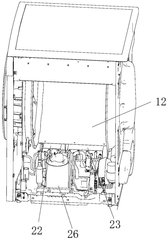
[0004] The structure of these two clothes dryers is very different, and the commonality of the production parts is low, and the existing heat pump clothes dryer adopts a vertical compressor, and the compressor, evaporator, and condenser are placed at the bottom of the drum (see figure 1 ): The compressor and heat exchanger are listed on the left and right sides. The volume of the evaporator and condenser each occupies about half of the bottom space. Due to the limitation of the height of the bottom space of the drum, the compressor cannot be selected with a large capacity. The evaporator, The condenser also cannot have enough dehumidification and heating area, which leads to a long drying time of the heat pump dryer
Insufficient lint filtration in existing heat pump dryers can lead to clogging of the evaporator aluminum sheets in the heat pump module, resulting in reduced drying efficiency

Method used


Image

  • Heat-pump module and clothes dryer
  • Heat-pump module and clothes dryer
  • Heat-pump module and clothes dryer

Examples


Embodiment Construction

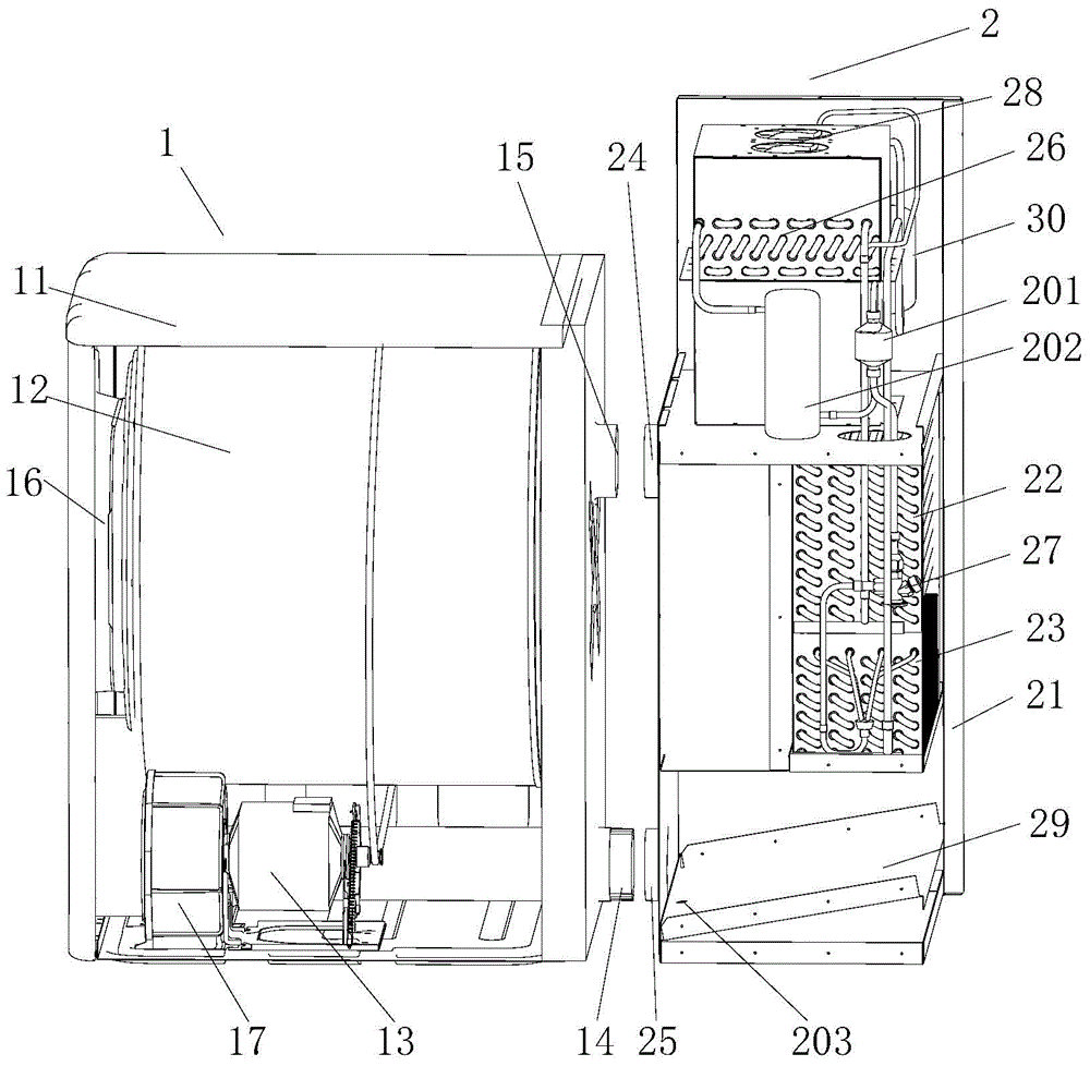
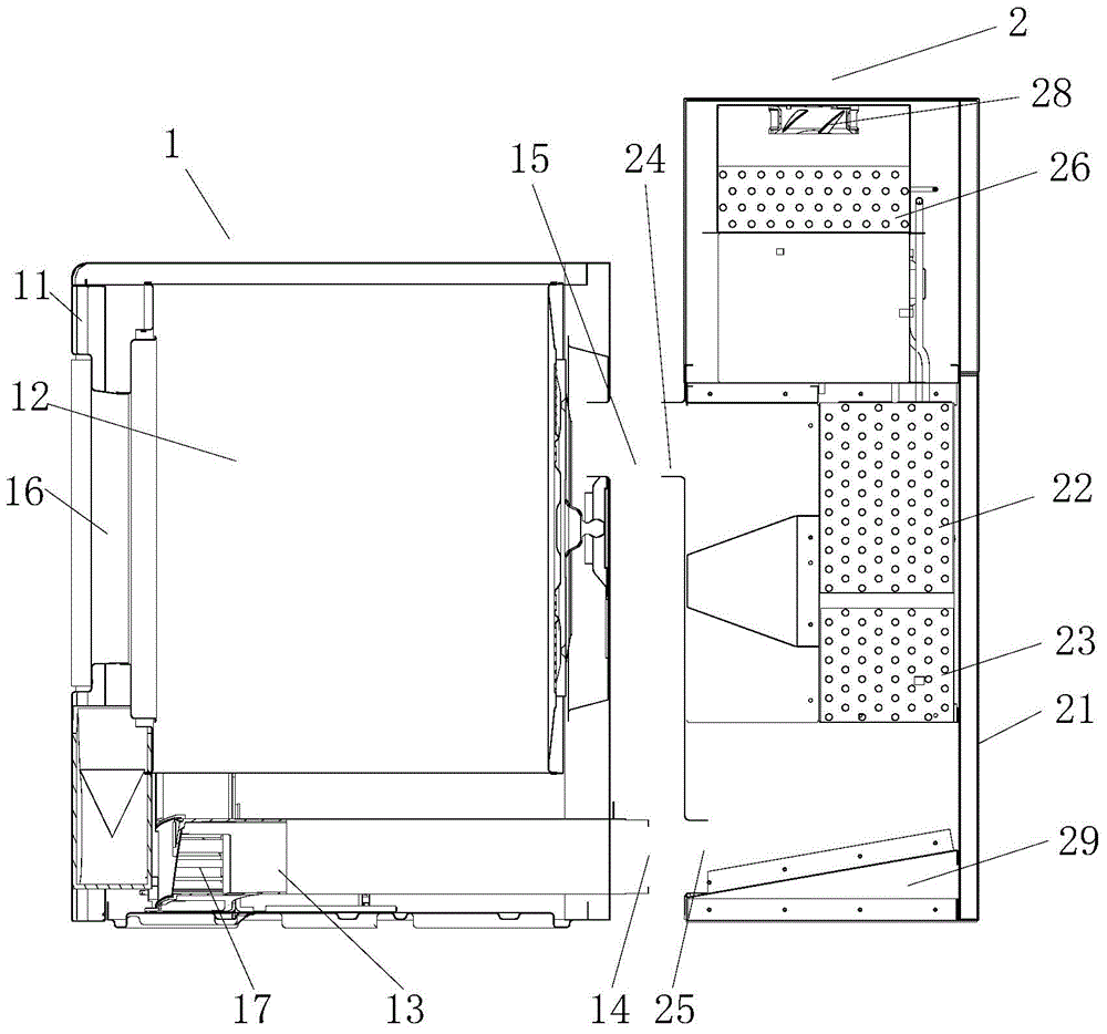
[0031] Such as figure 2 , image 3 As shown, a modular heat pump clothes dryer according to the present invention includes a clothes dryer body 1 and a heat pump module 2, and the clothes dryer body 1 includes a first shell 11 and a clothes dryer drum 12 inside the first shell 11 1. The driving device 13 of the drying drum 12, the first housing 12 is provided with a first air outlet 14 and a first air inlet 15 leading to the outside of the first housing 11; the heat pump module 2 includes a second housing 21, a second The evaporator 23, the condenser 22, the compressor 30 and the throttling device 27 in the casing 21, the second casing 21 is provided with a second air outlet 24 and a second air inlet 25 leading to the outside of the second casing 21; The clothes dryer body 1 and the heat pump module 2 are two separate and independent modules, which can be connected through the first air outlet 14 and the second air inlet 15, and the first air inlet 15 and the second air outl...


PUM


Abstract

The invention relates to a heat-pump module and a clothes dryer. The heat-pump module comprises a second shell, an evaporator, a condenser, a compressor, a throttling device, a second air outlet and a second air inlet. The second air outlet and the second air inlet are communicated with the outside of the second shell. The clothes dryer further comprises a clothes dryer body. The clothes dryer body comprises a first shell, a clothes drying rotary drum, a driving device, a first air outlet and a first air inlet, the first air outlet and the first air inlet are communicated with the outside of the first shell, the clothes dryer body and the heat-pump module are two modules which are separated and independent from each other, the first air outlet can be connected with the second air inlet, and the first air inlet can be connected with the second air outlet, so that the clothes dryer body and the heat-pump module can be integrated with each other. The heat-pump module and the clothes dryer have the advantages that the heat-pump module and the clothes dryer are modularly assembled, accordingly, assembling processes can be simplified, the heat-pump module and the clothes dryer are convenient to transport, components of a direct discharging type clothes dryer and a heat-pump clothes dryer are universal, and the direct discharging type clothes dryer can be conveniently modified to obtain the heat-pump clothes dryer; the heat-pump module is arranged at the rear of the clothes dryer, the heat exchange areas of the condenser and the evaporator can be enlarged, accordingly, the clothes drying efficiency can be improved, the drying time can be shortened, and energy can be saved.

Description

technical field [0001] The invention relates to the field of clothes dryers, in particular to a heat pump module and a clothes dryer using the heat pump module. Background technique [0002] The existing in-line clothes dryer includes a drum, a fan, a motor for driving the drum and the fan to rotate, a casing for accommodating the above-mentioned device, and a clothes inlet on one side of the casing. The motor drives the drum to rotate, and at the same time, the fan guides the air to enter the drum after being heated by the heating pipe through the air inlet. The moisture in the clothes is heated and turned into steam to make the air become humid air, and then discharged from the air outlet to the outside environment to realize the drying of clothes. [0003] The structure of the existing heat pump drying tumble dryer is as follows: a rotating cylinder is arranged in the casing, and a clothes input opening is arranged in the front of the rotating cylinder, which can be opene...

Claims


Application Information

Patent Timeline
Patent Type & Authority Applications(China)
IPC IPC(8): D06F58/02D06F58/20F25B30/06
CPCD06F58/02D06F58/206D06F58/24D06F58/26F25B30/06
Inventor 许升宋华诚田书君单世强
Owner HAIER GRP CORP
Learn More