

Laser-scattering-based air quality detecting system
A technology of air quality detection and laser emission system, which is applied in the direction of radio wave measurement system, measurement device, and utilization of re-radiation, etc. It can solve the problems of low signal-to-noise ratio, cumbersome procedures, time-consuming, etc., and achieve simple system structure and guaranteed detection Accuracy, overcoming the effect of unstable light source intensity
- Summary
- Abstract
- Description
- Claims
- Application Information
AI Technical Summary
Problems solved by technology
Method used
Image

Examples
Embodiment Construction
[0022] The specific implementation manner and working principle of the present invention will be further described in detail below in conjunction with the accompanying drawings.
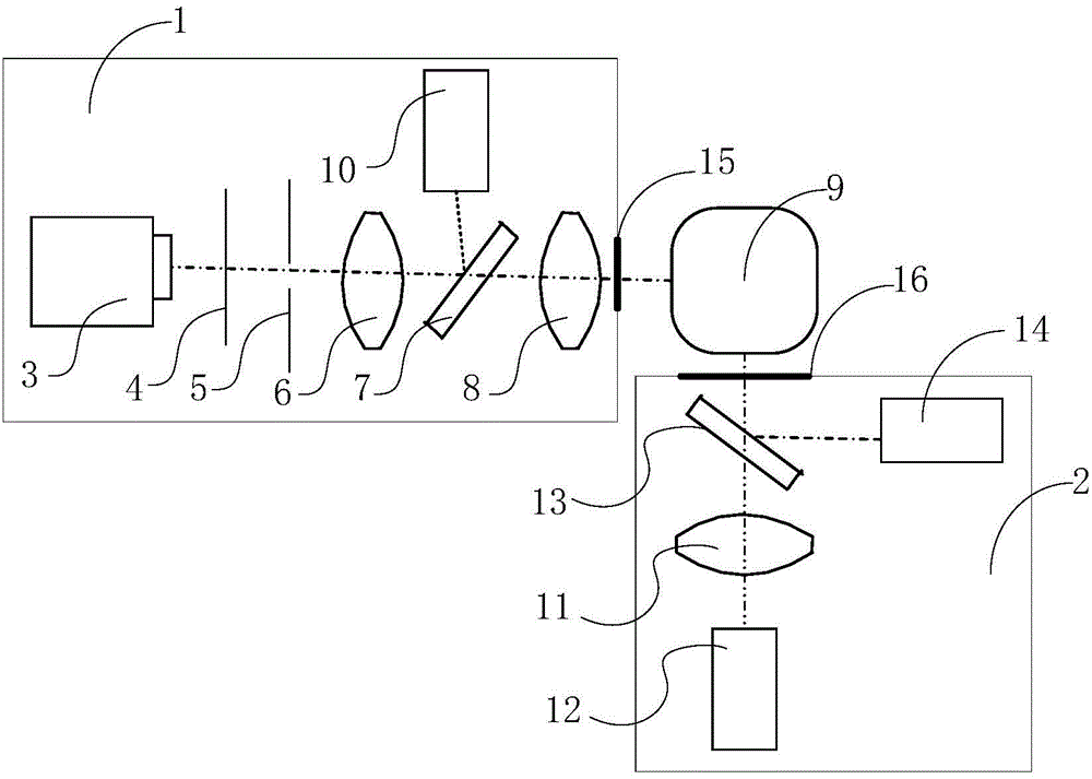
[0023] like figure 1 As shown, a kind of air quality detection system based on laser light scattering comprises a laser emitting system 1, a laser receiving system 2 and a sample cell 9, a laser light source 3 and a first photoelectric receiver 10 are arranged in the laser emitting system 1, so The laser light emitted by the laser light source 3 sequentially passes through the polarizer 4, the aperture stop 5, the first condenser lens 6, the first beam splitter 7 and the second condenser lens 8, and then enters the sample cell 9. Another path of light from the beam splitter 7 enters the first photoelectric receiver 10; the third condenser lens 11 and the second photoelectric receiver 12 are arranged in the laser receiving system 2, and the laser emitting system 1 emits The laser light incident on th...
PUM
 Abstract
Description
Claims
Application Information