
Fiber collimator having high-precision ray machine coaxiality, and assembling method thereof

A fiber collimator and optical-mechanical coaxial technology, which is applied in the coupling, installation, and light guide of optical waveguides, can solve the problem that the fiber collimator cannot be matched and adjusted, restricts the manufacturing efficiency of related optical devices, and restricts the optical fiber collimator. Use and other problems, to achieve the effect of simple structure, high optical-mechanical coaxiality, and solve limitations

Active Publication Date: 2015-03-18
安徽新高电气有限公司
View PDF5 Cites 2 Cited by
  • Summary
  • Abstract
  • Description
  • Claims
  • Application Information

AI Technical Summary

Problems solved by technology

Therefore, when fiber collimators are used in other optical devices, two matching fiber collimators often require a professional and complex alignment process, which not only restricts the manufacturing efficiency of related optical devices, but also affects the quality of optical devices. One of the reasons for the high cost
However, in some occasions, for example, in fiber optic rotary connectors, matching adjustments cannot be performed between two fiber collimators, which restricts the use of fiber collimators

Method used


Image

  • Fiber collimator having high-precision ray machine coaxiality, and assembling method thereof
  • Fiber collimator having high-precision ray machine coaxiality, and assembling method thereof
  • Fiber collimator having high-precision ray machine coaxiality, and assembling method thereof

Examples


Embodiment Construction

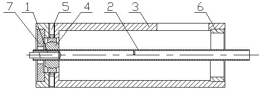
[0033] see figure 1 , the present invention is an optical fiber collimator with high-precision optical-mechanical coaxiality, which includes an optical fiber collimator 1, an inner sleeve 2 and an outer sleeve 3, and the optical fiber collimator 1 is arranged behind the inner sleeve 2 The outer sleeve 3 is set on the outer side of the inner sleeve 2, and the free end fixing part 6 of the collimator, the hinge 4 and the joint end of the collimator are sequentially arranged between the inner sleeve 2 and the outer sleeve 3 from front to back. The fixing part 7, the free end fixing part 6 of the collimator is located at the front end of the outer sleeve 3, the joint end fixing part 7 of the collimator is located at the rear end of the outer sleeve 3, and the hinge 4 is located at the joint end fixing part 7 of the collimator On the front side, the outer casing 3 is provided with screws 5 , and the hinge 4 is fixed by the screws 5 .

[0034] The free end fixing part 6 of the coll...


PUM


Abstract

The invention relates to a fiber collimator having high-precision ray machine coaxiality, and an assembling method thereof. The fiber collimator is composed of a fiber collimator body (1), an inner casing tube (2) and an outer casing tube (3). The fiber collimator body (1) is arranged at the rear end of the inner casing tube (2); and the outer casing tube (3) sleeves the outer side of the inner casing tube (2). A collimator free end fixed element (6), a hinge (4), and a collimator joint end fixed element (7) are successively arranged between the inner casing tube (2) and the outer casing tube (3) from front to back; the collimator free end fixed element (6) is arranged at the front end of the outer casing tube (3); the collimator joint end fixed element (7) is arranged at the rear end of the outer casing tube (3); and the hinge (4) is arranged at the front side of the collimator joint end fixed element (7). According to the fiber collimator and the assembling method thereof, the structure is simple; the ray machine coaxiality is high; a few adjusting steps are arranged; and the assembling process is simple.

Description

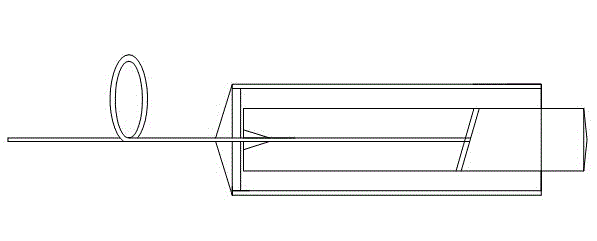
technical field [0001] The invention relates to an optical fiber collimator with high-precision optical-mechanical coaxiality and an assembly method thereof. Background technique [0002] In fiber optic devices, the fiber collimator is a key device. Traditional fiber collimators such as figure 1 As shown, it is mainly composed of optical fiber and its fixing structure, lens, and peripheral fixing parts. Due to the gap between the peripheral metal sleeve and glass tube, and the difference in material refractive index and behavior error between the fiber core and lens etc., the laser beam emitted from the lens is not parallel to the mechanical axis of the metal tube. Therefore, when fiber collimators are used in other optical devices, two matching fiber collimators often require a professional and complex alignment process, which not only restricts the manufacturing efficiency of related optical devices, but also affects the quality of optical devices. One of the reasons fo...

Claims


Application Information

Patent Timeline
Patent Type & Authority Applications(China)
IPC IPC(8): G02B27/30G02B6/38G02B7/00
CPCG02B7/006G02B27/30G02B6/3801
Inventor 周明宝章鹏雷小华周崇喜刘显明
Owner 安徽新高电气有限公司
Learn More