A self-cleaning optical system

An optical system and self-cleaning technology, which is applied in the field of optical systems, can solve the problems that plastic belts are not suitable for high-temperature processing environments, twisted, and plastic films are easily damaged or twisted by lasers.

Active Publication Date: 2015-03-18
UNIV COLLEGE DUBLIN NAT UNIV OF IRELAND DUBLIN
View PDF10 Cites 4 Cited by
  • Summary
  • Abstract
  • Description
  • Claims
  • Application Information

AI Technical Summary

Problems solved by technology

The advantage of rolling transparent tape is that it has a much larger surface area than that of rotating glazing, the disadvantage is that the plastic film is easily damaged or distorted by the laser, especially as debris begins to deposit and laser coupling becomes more efficient
So the belt has to move fast and the coil has to be quite long with all the mechanical problems that go with it
Also, plastic straps are not suitable for high-temperature processing environments because they will twist

Method used


Image

  • A self-cleaning optical system
  • A self-cleaning optical system
  • A self-cleaning optical system

Examples


Embodiment Construction

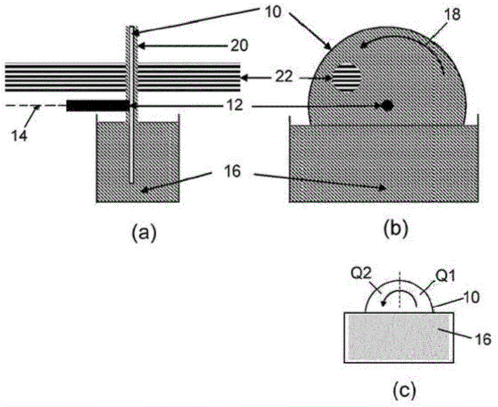
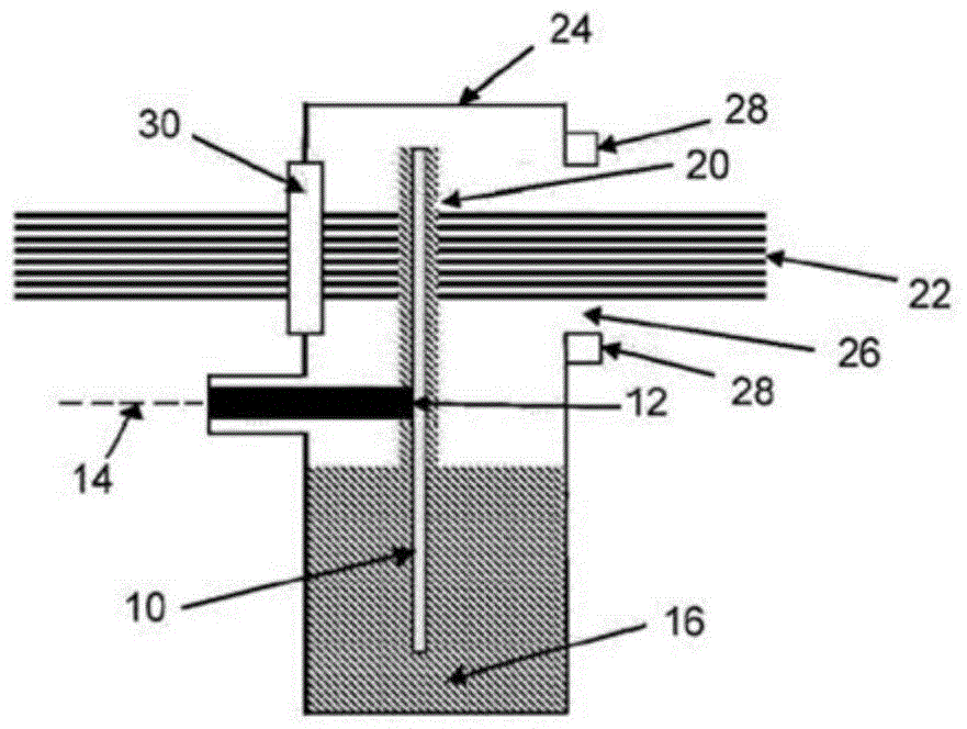
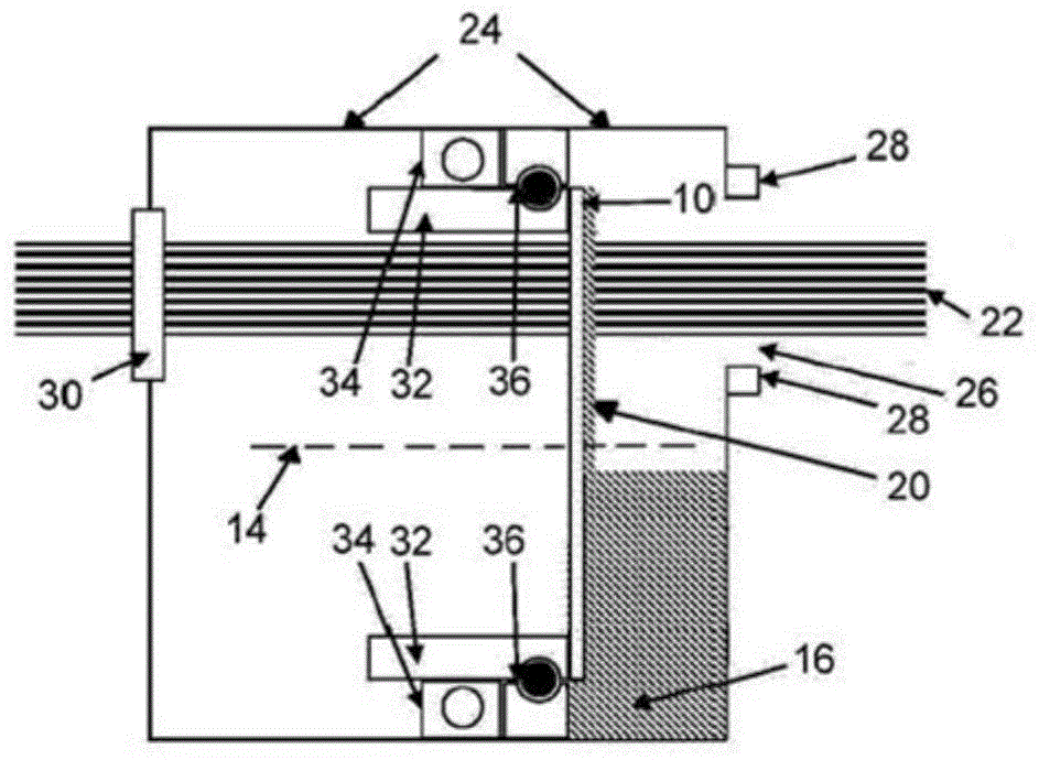
[0034] Please refer to figure 1, the first embodiment of the invention comprises a transparent glass plate 10 in the form of a flat optical disc. Plate 10 is mounted vertically on a shaft 12, rotatable in its own plane about a horizontal axis 14 passing through the center of the disc. Plate 10 may be made of glass, quartz, CaF2, MgF2, LiF or other transparent materials, as the case may be.

[0035] The lower part of the plate 10 is immersed in an oil pool 16 containing transparent oil. During operation, a motor (not shown) keeps the shaft 12 in continuous rotation - as indicated by arrow 18 - so that the lower half of the plate 10 is continuously rotated through the oil. Oils that may be used are fluorocarbon polymer oils, fluoropolymers of polyhexafluorooxypropylene, low vapor pressure polyphenylethyl ether, and other low pressure oils, as the case may be.

[0036] As the plate 10 emerges from the oil sump 16, a thin oil coating 20 remains on the glass. Initially, when th...


PUM


Abstract

A self-cleaning optical system for the transmission or reflection of light to and / or from a process region comprises a liquid bath and a transparent or reflective optical component continuously rotatable about a non-vertical axis so that a lower part of the component continuously rotates through the bath. When the component emerges from the bath,a coating of the liquid remains thereon which forms a substantially uniform film on at least a part of the component through which the light is transmitted or from which the light is reflected.

Description

technical field [0001] The present invention relates to an optical system that is primarily, but not exclusively, used in vacuum systems that are vulnerable to damage during plasma processing. However, the invention is more generally applicable to physical, chemical or other processes (including vacuum processes involving charged and neutral particles and photons (especially X-rays)) in which the process Debris from the process can strike the window, where light transmission is important. In the context of the present invention, "light" includes ultraviolet and infrared wavelengths as well as visible wavelengths, and the terms "optical" and "transparent" are to be construed accordingly. Background technique [0002] Typically, in these cases, the window needs to be replaced when it becomes too dirty, or a combination of window replacement, rotation, and air curtains are used. [0003] In U.S. Patent No. 7,501,145, during the pulsed laser deposition (PLD) process, the laser...

Claims


Application Information

Patent Timeline
IPC IPC(8): G01N21/15G02B27/00
CPCG02B27/0006G01N21/15G02B1/11
Inventor F.奥赖利K.费伊P.谢里登
Owner UNIV COLLEGE DUBLIN NAT UNIV OF IRELAND DUBLIN
Why Eureka
Try Eureka