Mesh-net type glass bottle annealing furnace

A glass bottle and mesh belt type technology, applied in the field of mesh belt type glass bottle annealing furnace, can solve the problems of uneven temperature difference change, fast damage of heating device, and too much heat loss at the front end of the furnace body.

Inactive Publication Date: 2015-03-25
YUNNAN ESHAN ZHIYUAN GLASS
View PDF6 Cites 0 Cited by
  • Summary
  • Abstract
  • Description
  • Claims
  • Application Information

AI Technical Summary

Problems solved by technology

[0003] Aiming at the problems in the prior art that the mesh-belt glass bottle annealing furnace has extremely uneven temperature difference between the front and back of the furnace body, the heat at the front end of the furnace body is dissipated from the furnace mouth, and the heating device at the front end of the furnace body is damaged quickly. The present invention Provide a mesh-belt type glass bottle annealing furnace, the furnace body is in the shape of a long strip, and the insulation wall is built outside. The front end of the furnace body is the bottle inlet end, and the front insulation door is installed on the port. For the rear insulation door, there is an interlayer in the middle and lower part of the furnace body. The interlayer divides the furnace body into a heat preservation cavity and a mesh belt rotary cavity. On the rear guide roller, tension roller and driving roller at the rear end of the furnace body, the upper surface of the mesh belt passes through the heat preservation chamber, and the lower mesh surface passes through the mesh belt rotary chamber, and heating devices are installed on both sides of the front end of the furnace body , an upper insulation layer is built above the insulation cavity, an upper insulation cavity is formed between the upper insulation layer and the top surface of the furnace body, a lower insulation layer is built below the insulation cavity, and between the lower insulation layer and the interlayer of the furnace body The lower heat insulation chamber is formed between them, and the heating device is installed in the hot air grooves on both sides of the front end of the furnace body. The upper opening of the hot air groove is designed in the upper heat insulation chamber, and the lower opening is designed in the heat preservation chamber. , the air inlet of the blower is installed at the lower part of the inner wall of the heat preservation cavity at the rear end of the furnace body, the air outlet of the blower is connected with the upper opening of the hot air groove, and the side wall of the front end of the furnace body is designed to connect the upper heat insulation cavity and the lower heat insulation cavity The air duct is equipped with a return fan at the rear end of the furnace body. The air inlet of the return fan is installed in the upper heat insulation chamber at the rear end of the furnace body. The air outlet of the return fan is installed vertically downward above the outlet of the heat preservation chamber. The compartment at the rear end of the body is designed with a hot air return slope

Method used


Image

  • Mesh-net type glass bottle annealing furnace
  • Mesh-net type glass bottle annealing furnace

Examples


Embodiment 1

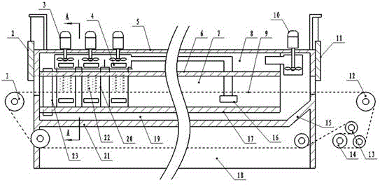
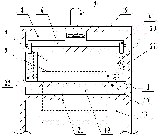
[0007] Embodiment one: if figure 1 and figure 2 As shown, a mesh-belt type glass bottle annealing furnace, the furnace body 5 is in the shape of a long strip, and the outer insulation wall is built. , the rear insulation door 11 is installed on the port, and the middle and lower part of the body of furnace 5 is provided with an interlayer 21. The interlayer 21 divides the body of furnace into a heat preservation chamber 7 and a mesh belt rotary chamber 18, and the front end of the mesh belt 9 is installed on the front end of the body of furnace. On the front guide roller 1, the rear end of the mesh belt is installed on the rear mesh roller 12, the tension roller 14 and the driving roller 13 at the rear end of the furnace body, the upper surface of the mesh belt 9 passes through the heat preservation cavity 7, and the lower mesh surface passes through the The mesh belt passes through the rotary cavity 18, and heating devices 22 are installed on both sides of the front end of ...


PUM


Abstract

The invention discloses a mesh-net type glass bottle annealing furnace which consists of a furnace body and a conveying mesh belt, wherein an upper thermal-insulating cavity and a lower thermal-insulating cavity are designed inside the heat-preservation cavity of the furnace body; heating devices are mounted inside hot air tanks on two sides of the front end of the furnace body; the upper openings of the hot air tanks are designed inside the upper thermal-insulating cavity; the lower openings are designed inside the heat-preservation cavity; air blowers are mounted at the upper part of the front end of the furnace body; the air inlets of the air blowers are mounted at the lower part of the side wall of the heat-preservation cavity in the rear end of the furnace body; the air outlets of the air blowers are connected with the upper openings of the hot air tanks; an air channel for connecting the upper thermal-insulating cavity and the lower thermal-insulating cavity is designed on the side wall of the front end of the furnace body; an air back fan is mounted at the rear end of the furnace body; the air inlet of the air back fan is mounted inside the upper thermal-insulating cavity in the rear end of the furnace body; the air outlet of the air back fan is vertically mounted downwards above the outer side of the air outlet of the heat-preservation cavity; a hot air guide inclined surface is designed on an insulating layer at the rear end of the furnace body. By adopting the technique, the energy conservation effect of the furnace body is remarkably improved, the repairing period is greatly prolonged, the temperature inside the furnace is uniformly reduced, the quality of a glass bottle is improved, and the damage rate is reduced.

Description

technical field [0001] The invention belongs to the technical field of glass bottle production equipment, and relates to a mesh belt type glass bottle annealing furnace. Background technique [0002] In the production process of glass bottles, the temperature of the glass bottles that are discharged from the glass melting furnace and then blown into shape is relatively high. They cannot be placed directly under natural conditions for cooling, and must be sent to the tempering furnace for slow and uniform annealing. , the annealing speed is too fast or the annealing speed fluctuates greatly, which will cause damage to the glass bottle, resulting in a decline in production quality and yield. In the prior art, the furnace body of the mesh-belt type glass bottle annealing furnace is in the shape of a long strip, and the insulation wall is built outside. The front end of the furnace body is the bottle inlet end, and the front insulation door is installed on the port. The rear in...

Claims


Application Information

Patent Timeline
IPC IPC(8): C03B25/00
CPCC03B25/00
Inventor 梁院平
Owner YUNNAN ESHAN ZHIYUAN GLASS
Why Eureka
Try Eureka