A trolley-type gas heat treatment furnace temperature control system and temperature control method

A heat treatment furnace and temperature control system technology, applied in heat treatment process control, heat treatment equipment, manufacturing tools, etc., can solve the problems of large temperature fluctuations in the temperature control area, reduced service life of equipment, uneven temperature changes, etc., to achieve the benefit of remote The effects of management, improving work efficiency and reducing production costs

Inactive Publication Date: 2016-08-24
SHANDONG IRON & STEEL CO LTD
View PDF4 Cites 0 Cited by
  • Summary
  • Abstract
  • Description
  • Claims
  • Application Information

AI Technical Summary

Problems solved by technology

In order to ensure the accuracy of temperature control, as well as the controllability of heating power and the uniformity of temperature in the furnace, the existing technology adopts multi-section partitions to control the furnace along the length direction, but as the depth of the furnace body increases, the heat flow is controlled by The side away from the flue surges to the side of the flue, and the temperature fluctuations in the temperature control area near the end of the flue and the end far away from the flue are relatively large, that is, during the entire temperature control process, there is a large temperature difference in the furnace, and the temperature changes Unevenness, which often affects the effect of heat treatment
In addition, the existing technology only solves the single heat treatment problem of the workpiece, and does not provide systematic process data analysis and production management functions in combination with the existing automation information technology, and most of the existing control systems use the panel of the temperature controller to set the process parameters. The service life of the equipment is greatly reduced, and the existing temperature control system and method have little consideration in terms of energy saving and environmental protection

Method used


Image

  • A trolley-type gas heat treatment furnace temperature control system and temperature control method

Examples


Embodiment Construction

[0029] In order to make the technical solution and advantages of the present invention clearer, the technical solution of the present invention will be completed below in conjunction with the accompanying drawings, taking a trolley-type gas heat treatment furnace with a size of 14m×6m×5m (length, width and height) as an example. described.

[0030] Among them, the loading capacity of the trolley-type gas-fired heat treatment furnace in this embodiment is ≤540t, the furnace body is a cuboid with fixed steel structure, and a liftable furnace door is provided on one side of the opening in the length direction.

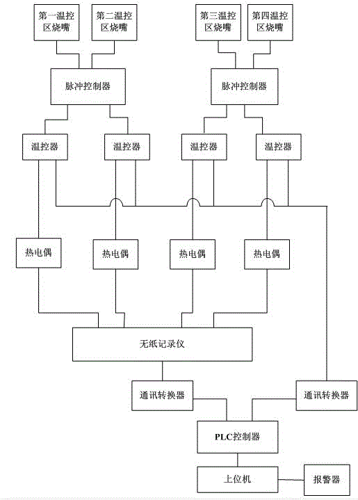
[0031] figure 1 The shown temperature control system of a trolley-type gas heat treatment furnace includes four temperature control zones distributed along the length direction of the furnace body, the first temperature control zone, the second temperature control zone, the third temperature control zone and the fourth temperature control zone. temperature control area. ...


PUM


Abstract

The invention provides a temperature control system and method of a gas car-bottom heat treating furnace. The temperature control system comprises a plurality of temperature control areas which are distributed along the length direction of a furnace body; burner nozzles are respectively mounted in two sides of each temperature control area; a thermocouple which is connected with a temperature controller is mounted on the top part of each temperature control area; the temperature controller of each temperature control area is connected with each burner nozzle in each temperature control area through a pulse controller. The temperature control system further comprises a PLC which is connected with each temperature controller through a communication convertor, wherein the PLC is also connected with an upper computer. According to the scheme, the temperature control system and method have the advantages that the temperature can be continuously and gradually varied, thus the temperature variation and adjustment which cause large temperature difference in the furnace can be avoided, and the temperature in the heat treating furnace can be controlled to be uniform conveniently.

Description

technical field [0001] The invention relates to the field of heat treatment furnace control, in particular to a trolley-type gas heat treatment furnace temperature control system and a temperature control method. Background technique [0002] Heat treatment equipment is the basis and guarantee for the realization of heat treatment process, which is directly related to the level of heat treatment technology and the quality of workpieces. [0003] At present, in the machining and casting industries, well-type heat treatment furnaces and trolley-type heat treatment furnaces are mostly used for heat treatment of large forgings and castings. Well-type furnaces are mostly used for heat treatment of shafts with long lengths, and resistance band heating is often used. The construction of the well-type furnace is complicated, requiring civil engineering to dig a well, and some depths can reach tens of meters, while the trolley furnace is a fixed semi-closed shell, and the workpiece i...

Claims


Application Information

Patent Timeline
Patent Type & Authority Patents(China)
IPC IPC(8): C21D11/00
Inventor 王轶李忠王云彪王宝国高丰
Owner SHANDONG IRON & STEEL CO LTD
Why Eureka
Try Eureka