Prefabricated steel reinforced concrete beam with transversal high-strength concrete clapboard, and construction method

A high-strength concrete, prefabricated assembly technology, applied in the direction of load-bearing elongated structural components, structural elements, building components, etc., can solve the problems of shortened construction period, poor overall performance, poor impermeability, etc., and achieve plastic rotation of the section Capacity assurance, reduction in construction man-hours, and improvement in construction performance

Active Publication Date: 2015-03-25
XI'AN UNIVERSITY OF ARCHITECTURE AND TECHNOLOGY
View PDF5 Cites 17 Cited by
  • Summary
  • Abstract
  • Description
  • Claims
  • Application Information

AI Technical Summary

Problems solved by technology

Compared with the cast-in-place concrete structure, the prefabricated structure can make the production of building components not affected and restricted by seasons, and realize industrial production. Since the components are poured and maintained in the factory, the quality of the components can be guaranteed, and the construction period is greatly shortened. Accelerate the construction progress and save a lot of formwork support, but it also has many shortcomings, such as poor overall performance, poor impermeability, unfavorable earthquake resistance, and certain deficiencies in use and aesthetics

Method used


Image

  • Prefabricated steel reinforced concrete beam with transversal high-strength concrete clapboard, and construction method
  • Prefabricated steel reinforced concrete beam with transversal high-strength concrete clapboard, and construction method
  • Prefabricated steel reinforced concrete beam with transversal high-strength concrete clapboard, and construction method

Examples


Embodiment Construction

[0051] The implementation of the present invention will be described in detail below in conjunction with the drawings and examples.

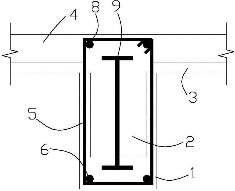
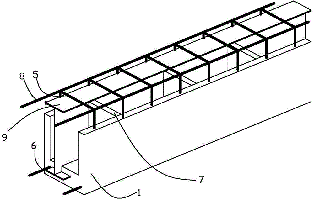
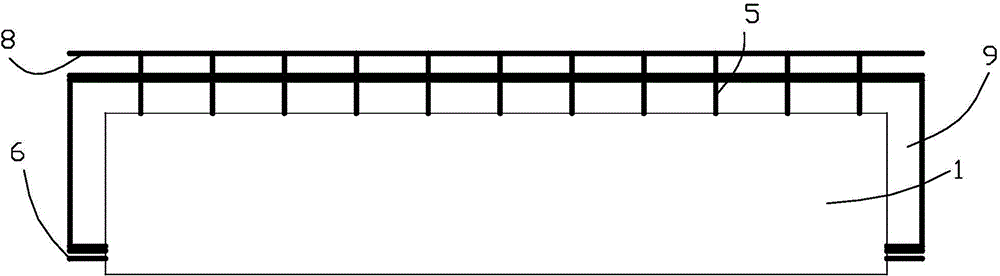
[0052] The present invention is a prefabricated assembled steel concrete beam with a transverse high-strength concrete partition, which adopts the idea of ​​partially prefabricated assembly part cast-in-place, and consists of a prefabricated part and a cast-in-place part, such as Figure 1 to Figure 10 As shown, it includes: prefabricated U-shaped high-strength concrete tank 1; cast-in-place ordinary concrete-2 filled in prefabricated U-shaped high-strength concrete tank 1; Sectional steel 9; a number of transverse high-strength concrete partitions 7 arranged in the prefabricated U-shaped high-strength concrete groove 1 and perpendicular to the groove length direction; a number of closed stirrups arranged in the prefabricated U-shaped high-strength concrete groove 1 and perpendicular to the groove length direction 5; a number of longitudinal bar...


PUM


Abstract

The invention discloses a prefabricated steel reinforced concrete beam with a transversal high-strength concrete clapboard. The prefabricated steel reinforced concrete beam with the transversal high-strength concrete clapboard is composed of a prefabricated part and a cast-in-situ part according to the thought of partially prefabricating and partially casting in situ. The prefabricated steel reinforced concrete beam with the transversal high-strength concrete clapboard comprises a prefabricated U-shaped high-strength concrete groove, cast-in-situ common concrete I filled in the prefabricated U-shaped high-strength concrete groove, sectional steel arranged in the length direction in the prefabricated U-shaped high-strength concrete groove and parallel to the length direction of the groove, a transversal high-strength concrete clapboard arranged in the prefabricated U-shaped high-strength concrete groove and vertical to the length direction of the groove, a plurality of closed stirrups arranged in the prefabricated U-shaped high-strength concrete groove and vertical to the length direction of the groove, a longitudinal bar I arranged at the bottom of the prefabricated U-shaped high-strength concrete groove and parallel to the length direction of the groove, and a cast-in-situ flange plate arranged at the top of the prefabricated U-shaped high-strength concrete groove. The prefabricated steel reinforced concrete beam with the transversal high-strength concrete clapboard, disclosed by the invention, is capable of increasing the longitudinal anti-shear action between prefabricated concrete and cast-in-situ concrete, preventing lateral breakages, and improving the cracking resistance, durability and fire resistance of the beam.

Description

technical field [0001] The invention belongs to the technical field of construction, in particular to a prefabricated steel concrete beam with a transverse high-strength concrete partition and a construction method. Background technique [0002] In the modern reinforced concrete structure, the earliest and most widely used structural form is the cast-in-place reinforced concrete structure, which is a structure formed by setting up formwork on site and integrally pouring, and has the advantages of good overall performance, high rigidity, and good seepage resistance. , At the same time, it is also highly adaptable to buildings with irregular shapes and flexible spaces. However, there are also many disadvantages in the process of use, such as on-site formwork and construction, many construction procedures, a large amount of labor, a large amount of materials, a long cycle, and high costs, which have not played a role in creating a resource-saving and environment-friendly societ...

Claims


Application Information

Patent Timeline
Patent Type & Authority Applications(China)
IPC IPC(8): E04C3/293
Inventor 于云龙杨勇马宁郭宇翔杨洋薛亦聪
Owner XI'AN UNIVERSITY OF ARCHITECTURE AND TECHNOLOGY
Why Eureka
Try Eureka