Valve element of proportional electromagnetic valve and proportional electromagnetic valve with valve element

A proportional solenoid valve, valve core technology, applied in the valve operation/release device, valve details, valve device and other directions, can solve the problems of dynamic performance impact, thin wall easily deformed, difficult processing, etc., to reduce eccentric wear, liquid flow direction Optimized, easy to process effects

Active Publication Date: 2015-03-25
北油电控燃油喷射系统(天津)有限公司
View PDF7 Cites 4 Cited by
  • Summary
  • Abstract
  • Description
  • Claims
  • Application Information

AI Technical Summary

Problems solved by technology

[0002] The spool of the traditional high-pressure common rail pump proportional solenoid valve adopts the type of opening two flow metering holes on the sleeve-shaped spool to measure the injection volume. Refer to the attached figure 1 As shown, first of all, with this type of valve core 8, the wall thickness of the valve core 8 is very thin, and the thin wall is relatively easy to deform during the process of ensuring the precise clearance between the outer circle of the valve core 8 and the static iron valve seat 7
Secondly, in order to ensure precise control of the liquid flow, two special-shaped flow holes are symmetrically opened on a specific position of the valve core, such as a valve port with a trapezoidal shape, and in the case of a small area, it is necessary to ensure the strict size of the small hole Tolerance, the two small holes must ensure the same axial position, which is very difficult to process. Traditional processing methods are difficult to meet the above processing requirements. It is necessary to re-purchase advanced processing equipment for this purpose, and the cost is very high.
In addition, the spool of the traditional proportional solenoid valve adopts radial overflow, and the liquid fuel flows through the valve port on the spool in two directions. The impact of the fluctuation of the liquid flow on the valve will affect the dynamic performance
[0003] This shows that the spool of above-mentioned existing proportional solenoid valve obviously still has inconvenience and defect in structure, method and use, and needs to be further improved urgently

Method used


Image

  • Valve element of proportional electromagnetic valve and proportional electromagnetic valve with valve element
  • Valve element of proportional electromagnetic valve and proportional electromagnetic valve with valve element
  • Valve element of proportional electromagnetic valve and proportional electromagnetic valve with valve element

Examples


Embodiment 1

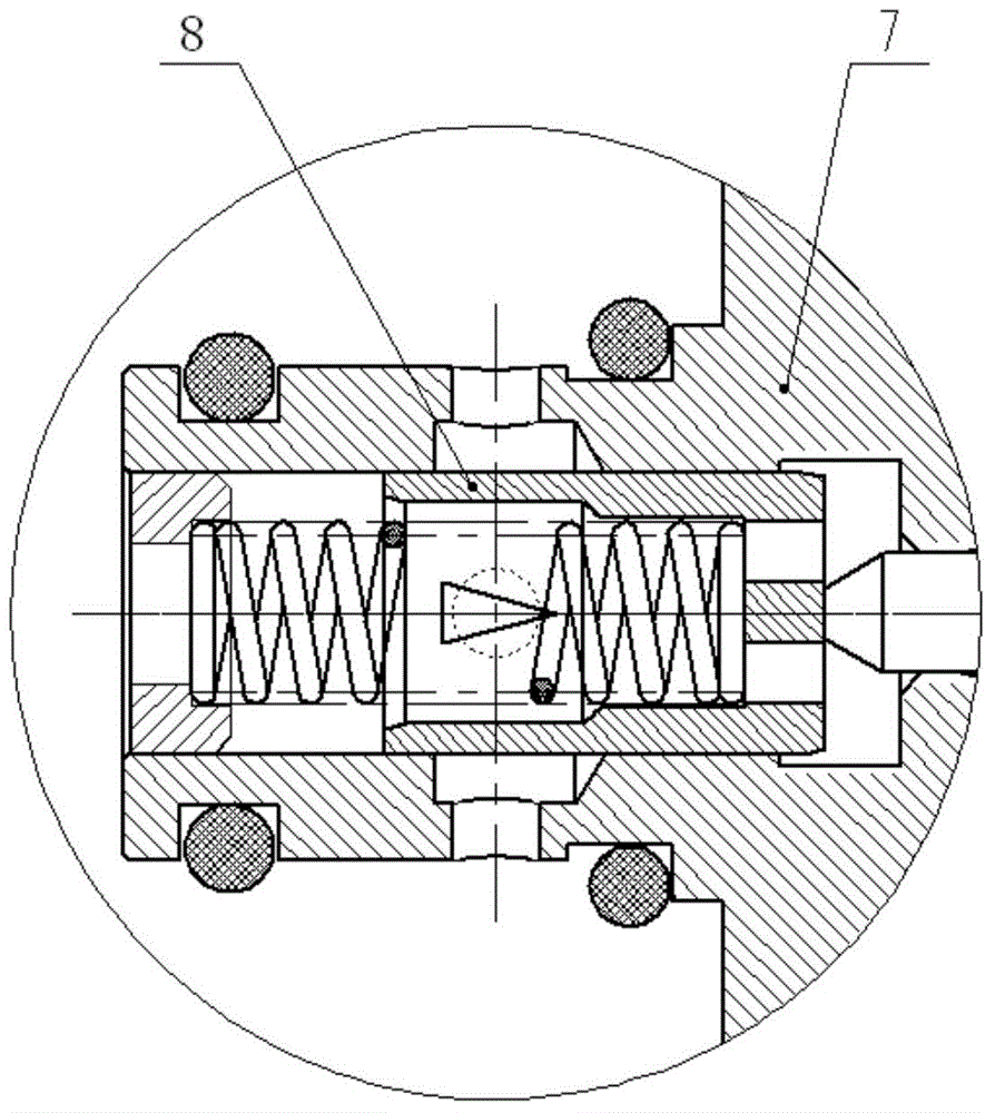
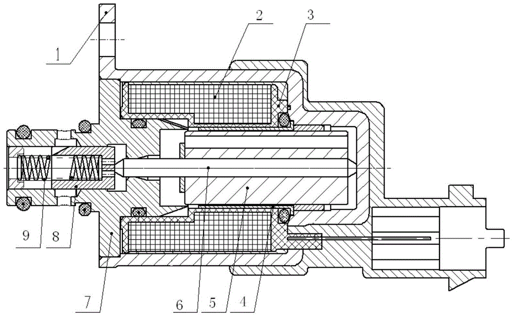
[0024] Embodiment one, with reference to the attached figure 2 As shown, the proportional solenoid valve of the present invention includes a housing 1, an electromagnetic coil 2, a skeleton 3 for winding the electromagnetic coil 2, a guide sleeve 4 inside the skeleton 3, a moving iron core 5 inside the guide sleeve 4, an interference The push rod 6 installed on the moving iron core 5, the static iron valve seat 7 assembled on the front end of the solenoid valve, the valve core 8 and the adjustment spring 9 located in the inner hole of the static iron valve seat 7. The tail of the proportional solenoid valve housing 1 is encapsulated by injection molding, and the head of the push rod 6 bears against the rear end plane of the spool 8 to push the spool 8 forward. The adjustment spring 9 is located at the other end of the spool 8 and can push the spool 8 to move backward. The inner wall of the static iron valve seat 7 is provided with an inner annular groove communicating with t...

Embodiment 2

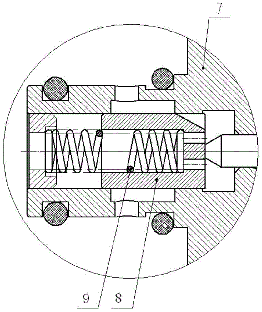
[0028] Embodiment two, referring to the attached image 3 As shown, the difference between this embodiment and the first embodiment is that the spool described in the first embodiment belongs to the proportional solenoid valve in the form of power-off normally open, while the spool in this embodiment belongs to the form of power-off normally closed Proportional solenoid valve spool, that is, when the current is zero, the flow characteristic of the solenoid valve is 0. The specific structure of the spool in this embodiment is that a plurality of flow regulating grooves are uniformly arranged on the outer circumference of the rear end of the spool 8, such as 3 evenly distributed flow regulating grooves or 2 symmetrically distributed flow regulating grooves. The rest of this embodiment is the same as the first embodiment, and will not be repeated here.

Embodiment 3

[0029] Embodiment three, with reference to the attached Figure 4 As shown, the difference between this embodiment and the first embodiment is that the valve core 8 is a cylindrical valve core without an inner cavity, and the adjustment spring 9 bears against the front end of the valve core 8 . The spool 8 is provided with more than one oil hole along the axial direction, which can balance the hydraulic pressure at both ends of the spool 8 and reduce the blockage during movement. The rest of this embodiment is the same as the first embodiment, and will not be repeated here.


PUM


Abstract

The invention discloses a valve element of a proportional electromagnetic valve. The valve element is installed in an inner hole of a static iron valve seat of the proportional electromagnetic valve. The axial position of the valve element is adjusted through the effect between a push rod and an adjusting spring. Two or more evenly-distributed flow adjusting grooves are formed in the outer circumferential wall of one end of the valve element and are axial flow passing grooves, and the notch sectional area of each flow adjusting groove is the largest at the end of the valve element and gradually reduced to zero along the outer circumferential wall of the valve element. The invention further provides the proportional electromagnetic valve with the valve element. By the axial flow passing flow adjusting grooves, liquid directly flows to a high-pressure pump oil channel through the flow adjusting grooves, the environment of a flow field is improved, the interaction effect between liquid pulsation and valve element final motion is reduced, the evenly-distributed flow adjusting grooves are good in alignment, the flow direction of the liquid is better optimized, and eccentric wear caused by long time work of the valve element is reduced. The valve element is reasonable in structural design and easy to machine, and the wall thickness of the valve element is increased, so that deformation of the valve element is not likely to happen.

Description

technical field [0001] The invention relates to the field of high-pressure common rail components, in particular to a valve core of a proportional solenoid valve and a proportional solenoid valve using the valve core. Background technique [0002] The spool of the traditional high-pressure common rail pump proportional solenoid valve adopts the type of opening two flow metering holes on the sleeve-shaped spool to measure the injection volume. Refer to the attached figure 1 As shown, first of all, with this type of valve core 8, the wall thickness of the valve core 8 is very thin, and the thin wall is relatively easy to deform during the process of ensuring the precise clearance between the outer circle of the valve core 8 and the static iron valve seat 7. Secondly, in order to ensure precise control of the liquid flow, two special-shaped flow holes are symmetrically opened on a specific position of the valve core, such as a valve port with a trapezoidal shape, and in the cas...

Claims


Application Information

Patent Timeline
Patent Type & Authority Applications(China)
IPC IPC(8): F16K31/06
CPCF16K31/06
Inventor 张建明
Owner 北油电控燃油喷射系统(天津)有限公司
Why Eureka
Try Eureka